(!)Due to Microsoft's end of support for Internet Explorer 11 on 15/06/2022, this site does not support the recommended environment.
63,000 Stock items for Same Day Shipping
63,000 Item Stok untuk Pengiriman di Hari yang Sama
Search by Category / Brand
Pencarian dengan
Kategori / Merek
Search by Category Pencarian dengan Kategori
- Automation Components
A wide variety of standard and configurable components for factory automation engineers in industries such as automotive, semiconductor, packaging, medical and many more.
- Linear Motion
- Rotary Motion
- Connecting Parts
- Rotary Power Transmission
- Motors
- Conveyors & Material Handling
- Locating, Positioning, Jigs & Fixtures
- Inspection
- Sensors, Switches
- Pneumatics, Hydraulics
- Vacuum Components
- Hydraulic Equipment
- Discharging / Painting Devices
- Pipe, Tubes, Hoses & Fittings
- Modules, Units
- Heaters, Temperature Control
- Framing & Support
- Casters, Leveling Mounts, Posts
- Doors, Cabinet Hardware
- Springs, Shock Absorbers
- Adjusting, Fastening, Magnets
- Antivibration, Soundproofing Materials, Safety Products
- Fasteners
A good selection of accessories such as screws, bolts, washers and nuts that you may need for your daily engineering usage.
- Materials
Browse industrial materials ranging from heat insulating plates, sponges, to metal and plastic materials in different sizes to meet your various applications.
- Wiring Components
A wide variety of wiring parts for connecting and protecting control and PC parts including Connectors, Cables, Electric Wires, Crimping Terminals and more.
- LAN Cables / Industrial Network Cables
- Cables by Application
- Cables with Connectors
- RS232 / Personal Computers / AV Cables
- Wires/Cables
- Connectors (General Purpose)
- Crimp Terminals
- Zip Ties
- Cable Glands
- Cable Bushings/Clips/Stickers
- Screws/Spacers
- Cable Accessories
- Tubes
- Protection Tubes
- Ducts/Wiremolds
- General Purpose Tools
- Dedicated Tools
- Soldering Supplies
- Electrical & Controls
A wide variety of controls and PC parts for electrical engineers including Controls, Powers, PC parts and more.
- Cutting Tools
A wide variety of cutting tools for many uses and work materials including End Mills, Drills, Cutters, Reamers, Turning Tools and more.
- Carbide End Mills
- HSS End Mills
- Milling Cutter Inserts/Holders
- Customized Straight Blade End Mills
- Dedicated Cutters
- Turning Tools
- Drill Bits
- Screw-Hole-Related Tools
- Reamers
- Chamfering / Centering Tools
- Fixtures Related to Cutting Tools
- Step Drills
- Hole Saws
- Clean Key Cutters
- Core Drills (Tip Tools)
- Magnetic Drilling Machine Cutters
- Drill Bits for Electric Drilling Machines
- Woodworking Drill Cutters
- Drills for Concrete
- Processing Tools
A wide variety of tools and supplies used in processing including Machine Tools, Measurement Tools, Grinding and Polishing Supplies and more.
- Material Handling & Storage
A wide variety of goods used in shipment, material handling and warehouse including Tape supplies, Stretch film, Truck, Shelf, Crane and more.
- Tape Supplies
- Cushioning Materials
- Stretch Films
- Cardboard
- Plastic Bags
- PP Bands
- Magic Tapes / Tying Belts
- Rubber Bands
- Strings/Ropes
- Cable Ties
- Tags
- Labelers
- Unpacking Cutters
- Packing Support Equipment
- Cloth Sheets for Packing
- Conveyance/Dolly Carts
- Tool Wagons
- Tool Cabinets / Container Racks
- Lifters / Hand Pallets
- Container Pallets
- Storage Supplies
- Shelves/Racks
- Work Benches
- Suspended Clamps/Suspended Belts
- Jack Winches
- Chain Block Cranes
- Bottles/Containers
- Bicycle Storage Area
- Safety & General Supplies
A large variety of goods for every kind of factories and offices including Protection items, Cleaning supplies, sanitations, office supplies and more.
- Lab & Clean Room Supplies
A large variety of items used in R&D and Clean Room including research Equipment, Laboratory Essentials, Analysis Supplies, Clean Environment-Related Equipment and more.
- Press Die Components
Choose from thousands of standard stamping die components including Punch & Die, Gas Springs, Guide Components, Coil Springs and many more.
- Plastic Mold Components
Browse our wide variety of mold components including Ejector Pins, Sleeves, Leader Components, Sprue Bushings and many more.
- Ejector Pins
- Sleeves, Center Pins
- Core Pins
- Sprue bushings, Gates, and other components
- Date Mark Inserts, Recycle Mark Inserts, Pins with Gas Vent
- Undercut, Plates
- Leader Components, Components for Ejector Space
- Mold Opening Controllers
- Cooling or Heating Components
- Accessories, Others
- Components of Large Mold, Die Casting
- Injection Molding Components
Browse our injection molding components including Heating Items, Couplers, Hoses and more.
- Injection Molding Machine Products
- Accessories of Equipment
- Auxiliary Equipment
- Air Nippers
- Air Cylinders
- Air Chuck for Runner
- Chuck Board Components
- Frames
- Suction Components
- Parallel Air Chuck
- Special Air Chuck
- Chemical for Injection Molding
- Mold Maintenance
- Heating Items
- Heat Insulation Sheets
- Couplers, Plugs, One-touch Joints
- Tubes, Hoses, Peripheral Components
- Komponen Mekanis
- Linear Motion
- Rotary Motion
- Connecting Parts
- Rotary Power Transmission
- Motors
- Conveyors & Material Handling
- Locating, Positioning, Jigs & Fixtures
- Inspection
- Sensors, Switches
- Pneumatics, Hydraulics
- Vacuum Components
- Hydraulic Equipment
- Discharging / Painting Devices
- Pipe, Tubes, Hoses & Fittings
- Modules, Units
- Heaters, Temperature Control
- Framing & Support
- Casters, Leveling Mounts, Posts
- Doors, Cabinet Hardware
- Springs, Shock Absorbers
- Adjusting, Fastening, Magnets
- Antivibration, Soundproofing Materials, Safety Products
- Sekrup, Baut, Washer, Nut
- Material
- Komponen Kabel
- LAN Cables / Industrial Network Cables
- Cables by Application
- Cables with Connectors
- RS232 / Personal Computers / AV Cables
- Wires/Cables
- Connectors (General Purpose)
- Crimp Terminals
- Zip Ties
- Cable Glands
- Cable Bushings/Clips/Stickers
- Screws/Spacers
- Cable Accessories
- Tubes
- Protection Tubes
- Ducts/Wiremolds
- General Purpose Tools
- Dedicated Tools
- Soldering Supplies
- Elektrikal & Kontrol
- Peralatan Pemotong
- Carbide End Mills
- HSS End Mills
- Milling Cutter Inserts/Holders
- Customized Straight Blade End Mills
- Dedicated Cutters
- Turning Tools
- Drill Bits
- Screw-Hole-Related Tools
- Reamers
- Chamfering / Centering Tools
- Fixtures Related to Cutting Tools
- Step Drills
- Hole Saws
- Clean Key Cutters
- Core Drills (Tip Tools)
- Magnetic Drilling Machine Cutters
- Drill Bits for Electric Drilling Machines
- Woodworking Drill Cutters
- Drills for Concrete
- Peralatan Produksi
- Penanganan Material & Penyimpanan
- Tape Supplies
- Cushioning Materials
- Stretch Films
- Cardboard
- Plastic Bags
- PP Bands
- Magic Tapes / Tying Belts
- Rubber Bands
- Strings/Ropes
- Cable Ties
- Tags
- Labelers
- Unpacking Cutters
- Packing Support Equipment
- Cloth Sheets for Packing
- Conveyance/Dolly Carts
- Tool Wagons
- Tool Cabinets / Container Racks
- Lifters / Hand Pallets
- Container Pallets
- Storage Supplies
- Shelves/Racks
- Work Benches
- Suspended Clamps/Suspended Belts
- Jack Winches
- Chain Block Cranes
- Bottles/Containers
- Bicycle Storage Area
- Perlengkapan Keamanan & Umum
- Perlengkapan Sanitasi & Lab
- Komponen Press Die
- Komponen Plastik Mold
- Ejector Pins
- Sleeves, Center Pins
- Core Pins
- Sprue bushings, Gates, and other components
- Date Mark Inserts, Recycle Mark Inserts, Pins with Gas Vent
- Undercut, Plates
- Leader Components, Components for Ejector Space
- Mold Opening Controllers
- Cooling or Heating Components
- Accessories, Others
- Components of Large Mold, Die Casting
- Komponen Injeksi Moulding
- Injection Molding Machine Products
- Accessories of Equipment
- Auxiliary Equipment
- Air Nippers
- Air Cylinders
- Air Chuck for Runner
- Chuck Board Components
- Frames
- Suction Components
- Parallel Air Chuck
- Special Air Chuck
- Chemical for Injection Molding
- Mold Maintenance
- Heating Items
- Heat Insulation Sheets
- Couplers, Plugs, One-touch Joints
- Tubes, Hoses, Peripheral Components
Search by Brand Pencarian dengan Merek


This translation is a Google translation Terjemahan ini adalah terjemahan Google
- Sehubungan dengan adanya Peraturan Baru Kementerian Perdagangan No.36 Tahun 2023 tentang Pembatasan Impor Barang, MISUMI Indonesia melakukan tindakan pencegahan. Lihat informasi detailnya di sini
Due to New Regulation of Ministry Of Trade No.36 of 2023 concerning retrictions on imports of goods, MISUMI Indonesia do precautions measure. See detail information here - Nomor telepon alternatif Kontak Layanan Pelanggan : 021-29182911| 021-29182991 | 021-29182997 | 021-29182998
Alternative telephone number Contact Customer Service: 021-29182911 | 021-29182991 | 021-29182997 | 021-29182998
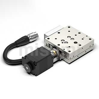
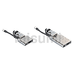
X-Axis Motorized Positioning Stages
- Volume Discount
Part Number
Configured Part Number is shown.
Product Overview of X-Axis stage
Product Feature of X-Axis stage
Feature 2. Strokes from 18 mm to 43 mm are made available by rearranging steel balls, extending lower seats, etc.
Feature 3. The 80 series motorized X-Axis stage has its sensor built-in to save space.
Feature 4: Quick disassembling is achieved by adding positioning holes to the upper and lower seats of the stage.
Feature 5. The positioning holes for 40/60/80 series have common diameters and positions, enabling a diversified combination of X-Axis stages with different dimensions.
Feature 6. The voltage of the limit sensor/driver has been expanded to 32 V, reducing burnout and other failures due to unstable voltage.
Dimensional Drawing of X-Axis stage
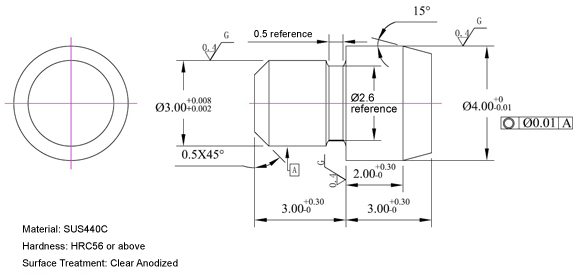
 The above figure shows the situation when cover L is selected. Please check the detailed dimensions by CAD data when selecting the cover R.Motor side connector cable lengths vary by model and are subject to the actual products.The purchased model already includes the X-Axis stage body, the corresponding driver and cable, so no need to purchase separately.
Specifications Overview of X-Axis stage
 Material Material |  Surface Treatment Surface Treatment | Movement (mm) | Load Capacity (N) | Single-Axis Accuracy Specification (μm) | |
| One-Way Positioning Accuracy | Repetitive Positioning Accuracy | ||||
| Equivalent to SUS440C | Electroless Nickel Plating | 18~43 | 98~117.6 | Within 20 | ±Within 5.0 |
Accessory: Locating pin Quantity: 4 pcs■ Movement
It refers to the distance that the X-Axis stage surface can move. (On each product page, illustration is made in the stroke center.)
■ Load capacity
It refers to the value of capacity that can be driven at the maximum speed with the maximum load that can be applied in the center of the X-Axis stage surface.
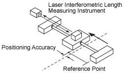
■ One-way positioning accuracy
It refers to the maximum difference between the measured distance (from the reference point to the position actually moved to) and the theoretical distance (from the reference point to the position that should be moved to as instructed)of each positioning point, which is measured and calculated within the full stroke after positioning is carried out in one direction at a certain interval from the reference point (the end of the stroke).
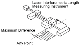
■ Repetitive positioning accuracy
Repeat positioning at the same point from the same direction 7 times, measure the offset of the stop position, and then calculate 1/2 of the maximum difference of this offset. Repeat this operation at 3 points between the center and bothends of the stroke, and define the maximum calculation value as the repetitive positioning accuracy.
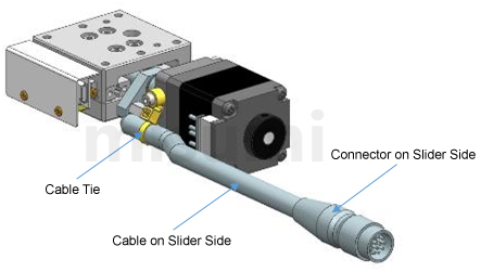
Usage Method of X-Axis stage
* 1 The cable in the dotted box is 2m cable
Related Documents of X-Axis stage
 Two-phase Stepper Motor Driver C-DR42A.
■ Drawing of the locating pin
Precautions of X-Axis stage
Operating environment: 10~50℃, 20~70% RH (without condensation)
Recommended operating environment: 22±5℃, 20~70%RH (without condensation)
Please avoid using this X-Axis stage in the following environments
① Dusty environment (especially metal powder)
② Environment with direct sunlight and thermal radiation
③ Environment near fire sources
④ Environment containing corrosive gases and flammable gases
⑤ Environment with splashing water and oil
⑥ Environment with strong vibration and impact
⑦ Environment containing organic solutions and salt
■X-Axis stage maintenance
A uniform maintenance standard is not available, and the maintenance method is subject to the type of grease and operating environment. Based on the driving conditions and guide types, make sure to check the grease once a month.
■ About wiring
The motors and sensors of this product are wired externally with cables and connectors. If the cable on the X-Axis stage side is frequently bent, it may cause the cable tie to break, and thus cause loosening of the motor terminal andsensor terminal, resulting in poor contact or core wire breakage. It is recommended to fix the connector on the X-Axis stage side during wiring.
 Drawings are for reference only
Application Industries of X-Axis stage
| Electronics/home appliance | Automotive | Medical | ||
 | 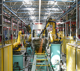 |  | ||
| Smart phone | Semiconductor | Lithium battery | ||
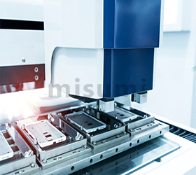 | 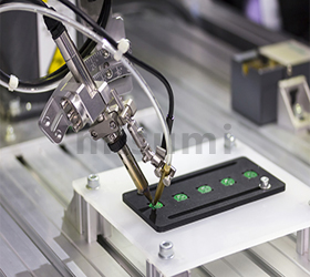 | 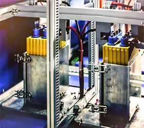 |
Related Products of X-Axis stage
| Stepper Driver | High-precision X-Axis Automatic X-Axis stage | Medium-precision X-Axis Automatic X-Axis stage | ||
 |  | 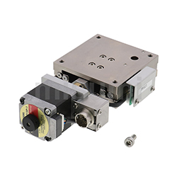 | ||
| Typical model: C-DR42A | Typical model: XMSG413-LA24-C-N | Typical model: XMBS415-L-N |
Part Number
CAD Data download and 3D preview are not available because the part number has not yet been determined.
- *In order to open the CAD Data download and 3D preview screen, the part number must be fixed.
- Please confirm the part number from "Specification / Dimension"on the left side, and then perform the CAD Data Download / 3D Preview operation.
| Part Number | Minimum order quantity | Volume Discount | Days to Ship | RoHS | Table Length (mm) | Cable Length (m) | Cover Position |
|---|---|---|---|---|---|---|---|
| 1 Piece(s) | Available | 10 Day(s) | - | 40 | 2 | L | |
| 1 Piece(s) | Available | 10 Day(s) | - | 40 | 4 | L | |
| 1 Piece(s) | Available | 10 Day(s) | - | 40 | 2 | R | |
| 1 Piece(s) | Available | 10 Day(s) | - | 40 | 4 | R | |
| 1 Piece(s) | Available | 10 Day(s) | - | 60 | 2 | L | |
| 1 Piece(s) | Available | 10 Day(s) | - | 60 | 4 | L | |
| 1 Piece(s) | Available | 10 Day(s) | 10 | 60 | 2 | R | |
| 1 Piece(s) | Available | 10 Day(s) | - | 60 | 4 | R | |
| 1 Piece(s) | Available | 10 Day(s) | - | 100 | 2 | L | |
| 1 Piece(s) | Available | 10 Day(s) | - | 100 | 4 | L | |
| 1 Piece(s) | Available | 10 Day(s) | - | 100 | 2 | R | |
| 1 Piece(s) | Available | 10 Day(s) | - | 100 | 4 | R | |
| 1 Piece(s) | Available | 10 Day(s) | - | 80 | 2 | L | |
| 1 Piece(s) | Available | 10 Day(s) | - | 80 | 4 | L | |
| 1 Piece(s) | Available | 10 Day(s) | - | 80 | 2 | R | |
| 1 Piece(s) | Available | 10 Day(s) | - | 80 | 4 | R |
Loading...
 The above figure shows the situation when cover L is selected. Please check the detailed dimensions by CAD data when selecting the cover R.Motor side connector cable lengths vary by model and are subject to the actual products.The purchased model already includes the positioning stage body, the corresponding driver and cable, so no need to purchase separately.
| Shape | Mechanical Specification | Accuracy Specification | Sensor | ||||||||||||
| Positioning stage surface (mm) | Movement (mm) | Load Capacity (N) | Weight (kg) | Resolution (Pulse) | Maximum Speed | One-Way Positioning Accuracy | Repetitive Positioning Accuracy | Invalid Motion | Parallelism | Motion Straightness | Motion Parallelism | Limit Sensor | Origin Sensor (ORG1) | ||
| X-Axis | 420 type | 40×40 | 18 | 98 | 0.4 | 5μm | 10 mm/sec | Within 20μm | Within ±5.0μm | 10μm | 30μm | 10μm | 20μm | Provided | Provided |
| 630 type | 60×60 | 28 | 0.6 | ||||||||||||
| 650 type | 60×100 | 43 | 0.8 | ||||||||||||
| 820 type | 80×80 | 20 | 117.6 | 0.8 | |||||||||||
■ Universal Specifications
| Feed Screw | Ball Screw Φ6, Lead 1mm | |
| Guide | Linear Ball Guide Type | |
| Motor | Shape | 2-Phase Stepper Motor |
| Step Angle | 1.8° | |
| Driver | Power Voltage | DC15~32V |
| Output current | 0.1~2.2A | |
| Pulse Signal Voltage | 5~24V | |
| Subdivision | 200~20000 | |
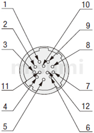
| Connector | Part Number | HR10A-10J-12P (HIROSE) |
| Receiving Side Part Number | HR10A-10P-12S (HIROSE) | |
| Sensor Substrate | Power Voltage | DC15~32V |
| Sensor Type | Micro Optical Sensor EE-SX4320 (OMRON) | |
| Control Output | NPN Open Collector Output | |
| Output Logic | When detecting (shading): output transistor OFF (non-conductive) | |
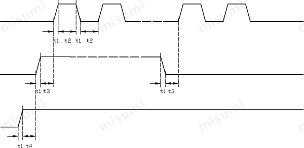
t1<0.1 us t2≥0.9 us t3≥10 us
t4: ENA (Enable Signal) t4 should be at least 10 μs ahead of DIR, and it is determined as high. Generally, ENA+ and ENA- are recommended to be suspended.
Basic Information
| Resolution(µm) | 5 | Motor, Motor Characteristics | 2-Phase Stepping Motor - Standard | Guide | Linear Ball Guide |
|---|---|---|---|---|---|
| Table Feeding Method | Ball Screw | Sensor | Limit + Home | Maximum Speed(mm/sec) | 10 |
| Lead | 1 | Driver | A | Parallelism(μm) | 30 |
| Motion Parallelism(μm) | 20 | Motion Straightness(μm) | 10 | Material | Equivalent to SUS440C |
- The specifications and dimensions of some parts may not be fully covered. For exact details, refer to manufacturer catalogs .
Frequently asked question (FAQ)
- Question: Can MISUMI motorized positioning stage be used directly after the purchase? What other accessories are needed for the actual drive?
- Answer: In addition to purchasing MISUMI automatic positioning stage (including the motor driver and 2m cable), the customer also needs to prepare 24V power supply and control unit by himself.
- Question: Why does my positioning stage only run in one direction?
-
Answer:
1. Maybe the directional signal is too weak, or the wiring is reversed, or the signal voltage is too high causing burnout of the internal current limiting resistor.
2. The pulse mode does not match. The signal mode must be consistent with the driver settings, otherwise the positioning stage will not rotate or will only run in one direction. - Question: What is the accuracy of the stepper motor? Is it cumulative?
- Answer: Generally, the accuracy of the stepper motor is 3 to 5% of the step angle. The single step deviation of the stepper motor will not affect the accuracy of the next step, so the accuracy of the stepper motor is not accumulated.
- Question: What is the allowable exterior temperature of the stepper motor?
- Answer: Too high temperature of the stepper motor will first demagnetize the magnetic material of the motor, resulting in torque decrease or even loss. Therefore, the maximum allowable temperature of the motor exterior should depend on the demagnetization point of different motor magnetic materials. Generally speaking, the demagnetization point of magnetic materials is above 130℃, so it is completely normal for the exterior temperature of the stepper motor to be around 80℃.
Tech Support
-
Credit Card
Kartu Kredit
-
Bank TransferTransfer Bank
MISUMI Contact
MISUMI Kontak
Copyright © MISUMI Corporation All Rights Reserved.
How can we improve?Bagaimana Kami bisa meningkatkan Pelayanan?
How can we improve?Bagaimana Kami bisa meningkatkan Pelayanan?
While we are not able to respond directly to comments submitted in this form, the information will be reviewed for future improvement.
Customer Privacy Policy Walaupun Kami tidak dapat langsung menjawab saran yang ditulis di lembar ini, informasinya akan kami review untuk peningkatan pelayanan dikemudian hari
Kebijakan Privacy
Thank you for your cooperation.Terima kasih atas kerjasama anda.
While we are not able to respond directly to comments submitted in this form, the information will be reviewed for future improvement.
Please use the inquiry form.
Customer Privacy Policy Walaupun Kami tidak dapat langsung menjawab saran yang ditulis di lembar ini, informasinya akan kami review untuk peningkatan pelayanan dikemudian hari
Silahkan pergunakan Forms Permintaan.
Kebijakan Privacy