(!)Due to Microsoft's end of support for Internet Explorer 11 on 15/06/2022, this site does not support the recommended environment.
63,000 Stock items for Same Day Shipping
63,000 Item Stok untuk Pengiriman di Hari yang Sama
Search by Category / Brand
Pencarian dengan
Kategori / Merek
Search by Category Pencarian dengan Kategori
- Automation Components
A wide variety of standard and configurable components for factory automation engineers in industries such as automotive, semiconductor, packaging, medical and many more.
- Linear Motion
- Rotary Motion
- Connecting Parts
- Rotary Power Transmission
- Motors
- Conveyors & Material Handling
- Locating, Positioning, Jigs & Fixtures
- Inspection
- Sensors, Switches
- Pneumatics, Hydraulics
- Vacuum Components
- Hydraulic Equipment
- Discharging / Painting Devices
- Pipe, Tubes, Hoses & Fittings
- Modules, Units
- Heaters, Temperature Control
- Framing & Support
- Casters, Leveling Mounts, Posts
- Doors, Cabinet Hardware
- Springs, Shock Absorbers
- Adjusting, Fastening, Magnets
- Antivibration, Soundproofing Materials, Safety Products
- Fasteners
A good selection of accessories such as screws, bolts, washers and nuts that you may need for your daily engineering usage.
- Materials
Browse industrial materials ranging from heat insulating plates, sponges, to metal and plastic materials in different sizes to meet your various applications.
- Wiring Components
A wide variety of wiring parts for connecting and protecting control and PC parts including Connectors, Cables, Electric Wires, Crimping Terminals and more.
- LAN Cables / Industrial Network Cables
- Cables by Application
- Cables with Connectors
- RS232 / Personal Computers / AV Cables
- Wires/Cables
- Connectors (General Purpose)
- Crimp Terminals
- Zip Ties
- Cable Glands
- Cable Bushings/Clips/Stickers
- Screws/Spacers
- Cable Accessories
- Tubes
- Protection Tubes
- Ducts/Wiremolds
- General Purpose Tools
- Dedicated Tools
- Soldering Supplies
- Electrical & Controls
A wide variety of controls and PC parts for electrical engineers including Controls, Powers, PC parts and more.
- Cutting Tools
A wide variety of cutting tools for many uses and work materials including End Mills, Drills, Cutters, Reamers, Turning Tools and more.
- Carbide End Mills
- HSS End Mills
- Milling Cutter Inserts/Holders
- Customized Straight Blade End Mills
- Dedicated Cutters
- Turning Tools
- Drill Bits
- Screw-Hole-Related Tools
- Reamers
- Chamfering / Centering Tools
- Fixtures Related to Cutting Tools
- Step Drills
- Hole Saws
- Clean Key Cutters
- Core Drills (Tip Tools)
- Magnetic Drilling Machine Cutters
- Drill Bits for Electric Drilling Machines
- Woodworking Drill Cutters
- Drills for Concrete
- Processing Tools
A wide variety of tools and supplies used in processing including Machine Tools, Measurement Tools, Grinding and Polishing Supplies and more.
- Material Handling & Storage
A wide variety of goods used in shipment, material handling and warehouse including Tape supplies, Stretch film, Truck, Shelf, Crane and more.
- Tape Supplies
- Cushioning Materials
- Stretch Films
- Cardboard
- Plastic Bags
- PP Bands
- Magic Tapes / Tying Belts
- Rubber Bands
- Strings/Ropes
- Cable Ties
- Tags
- Labelers
- Unpacking Cutters
- Packing Support Equipment
- Cloth Sheets for Packing
- Conveyance/Dolly Carts
- Tool Wagons
- Tool Cabinets / Container Racks
- Lifters / Hand Pallets
- Container Pallets
- Storage Supplies
- Shelves/Racks
- Work Benches
- Suspended Clamps/Suspended Belts
- Jack Winches
- Chain Block Cranes
- Bottles/Containers
- Bicycle Storage Area
- Safety & General Supplies
A large variety of goods for every kind of factories and offices including Protection items, Cleaning supplies, sanitations, office supplies and more.
- Lab & Clean Room Supplies
A large variety of items used in R&D and Clean Room including research Equipment, Laboratory Essentials, Analysis Supplies, Clean Environment-Related Equipment and more.
- Press Die Components
Choose from thousands of standard stamping die components including Punch & Die, Gas Springs, Guide Components, Coil Springs and many more.
- Plastic Mold Components
Browse our wide variety of mold components including Ejector Pins, Sleeves, Leader Components, Sprue Bushings and many more.
- Ejector Pins
- Sleeves, Center Pins
- Core Pins
- Sprue bushings, Gates, and other components
- Date Mark Inserts, Recycle Mark Inserts, Pins with Gas Vent
- Undercut, Plates
- Leader Components, Components for Ejector Space
- Mold Opening Controllers
- Cooling or Heating Components
- Accessories, Others
- Components of Large Mold, Die Casting
- Injection Molding Components
Browse our injection molding components including Heating Items, Couplers, Hoses and more.
- Injection Molding Machine Products
- Accessories of Equipment
- Auxiliary Equipment
- Air Nippers
- Air Cylinders
- Air Chuck for Runner
- Chuck Board Components
- Frames
- Suction Components
- Parallel Air Chuck
- Special Air Chuck
- Chemical for Injection Molding
- Mold Maintenance
- Heating Items
- Heat Insulation Sheets
- Couplers, Plugs, One-touch Joints
- Tubes, Hoses, Peripheral Components
- Komponen Mekanis
- Linear Motion
- Rotary Motion
- Connecting Parts
- Rotary Power Transmission
- Motors
- Conveyors & Material Handling
- Locating, Positioning, Jigs & Fixtures
- Inspection
- Sensors, Switches
- Pneumatics, Hydraulics
- Vacuum Components
- Hydraulic Equipment
- Discharging / Painting Devices
- Pipe, Tubes, Hoses & Fittings
- Modules, Units
- Heaters, Temperature Control
- Framing & Support
- Casters, Leveling Mounts, Posts
- Doors, Cabinet Hardware
- Springs, Shock Absorbers
- Adjusting, Fastening, Magnets
- Antivibration, Soundproofing Materials, Safety Products
- Sekrup, Baut, Washer, Nut
- Material
- Komponen Kabel
- LAN Cables / Industrial Network Cables
- Cables by Application
- Cables with Connectors
- RS232 / Personal Computers / AV Cables
- Wires/Cables
- Connectors (General Purpose)
- Crimp Terminals
- Zip Ties
- Cable Glands
- Cable Bushings/Clips/Stickers
- Screws/Spacers
- Cable Accessories
- Tubes
- Protection Tubes
- Ducts/Wiremolds
- General Purpose Tools
- Dedicated Tools
- Soldering Supplies
- Elektrikal & Kontrol
- Peralatan Pemotong
- Carbide End Mills
- HSS End Mills
- Milling Cutter Inserts/Holders
- Customized Straight Blade End Mills
- Dedicated Cutters
- Turning Tools
- Drill Bits
- Screw-Hole-Related Tools
- Reamers
- Chamfering / Centering Tools
- Fixtures Related to Cutting Tools
- Step Drills
- Hole Saws
- Clean Key Cutters
- Core Drills (Tip Tools)
- Magnetic Drilling Machine Cutters
- Drill Bits for Electric Drilling Machines
- Woodworking Drill Cutters
- Drills for Concrete
- Peralatan Produksi
- Penanganan Material & Penyimpanan
- Tape Supplies
- Cushioning Materials
- Stretch Films
- Cardboard
- Plastic Bags
- PP Bands
- Magic Tapes / Tying Belts
- Rubber Bands
- Strings/Ropes
- Cable Ties
- Tags
- Labelers
- Unpacking Cutters
- Packing Support Equipment
- Cloth Sheets for Packing
- Conveyance/Dolly Carts
- Tool Wagons
- Tool Cabinets / Container Racks
- Lifters / Hand Pallets
- Container Pallets
- Storage Supplies
- Shelves/Racks
- Work Benches
- Suspended Clamps/Suspended Belts
- Jack Winches
- Chain Block Cranes
- Bottles/Containers
- Bicycle Storage Area
- Perlengkapan Keamanan & Umum
- Perlengkapan Sanitasi & Lab
- Komponen Press Die
- Komponen Plastik Mold
- Ejector Pins
- Sleeves, Center Pins
- Core Pins
- Sprue bushings, Gates, and other components
- Date Mark Inserts, Recycle Mark Inserts, Pins with Gas Vent
- Undercut, Plates
- Leader Components, Components for Ejector Space
- Mold Opening Controllers
- Cooling or Heating Components
- Accessories, Others
- Components of Large Mold, Die Casting
- Komponen Injeksi Moulding
- Injection Molding Machine Products
- Accessories of Equipment
- Auxiliary Equipment
- Air Nippers
- Air Cylinders
- Air Chuck for Runner
- Chuck Board Components
- Frames
- Suction Components
- Parallel Air Chuck
- Special Air Chuck
- Chemical for Injection Molding
- Mold Maintenance
- Heating Items
- Heat Insulation Sheets
- Couplers, Plugs, One-touch Joints
- Tubes, Hoses, Peripheral Components
Search by Brand Pencarian dengan Merek


This translation is a Google translation Terjemahan ini adalah terjemahan Google
- Sehubungan dengan adanya Peraturan Baru Kementerian Perdagangan No.36 Tahun 2023 tentang Pembatasan Impor Barang, MISUMI Indonesia melakukan tindakan pencegahan. Lihat informasi detailnya di sini
Due to New Regulation of Ministry Of Trade No.36 of 2023 concerning retrictions on imports of goods, MISUMI Indonesia do precautions measure. See detail information here - Nomor telepon alternatif Kontak Layanan Pelanggan : 021-29182911| 021-29182991 | 021-29182997 | 021-29182998
Alternative telephone number Contact Customer Service: 021-29182911 | 021-29182991 | 021-29182997 | 021-29182998
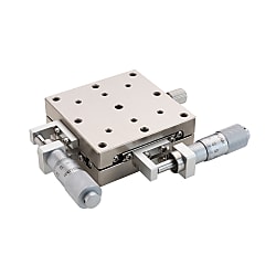
XY-Axis Manual Stages, Linear Ball Guide, Thin Type


- Volume Discount
Part Number
Configured Part Number is shown.
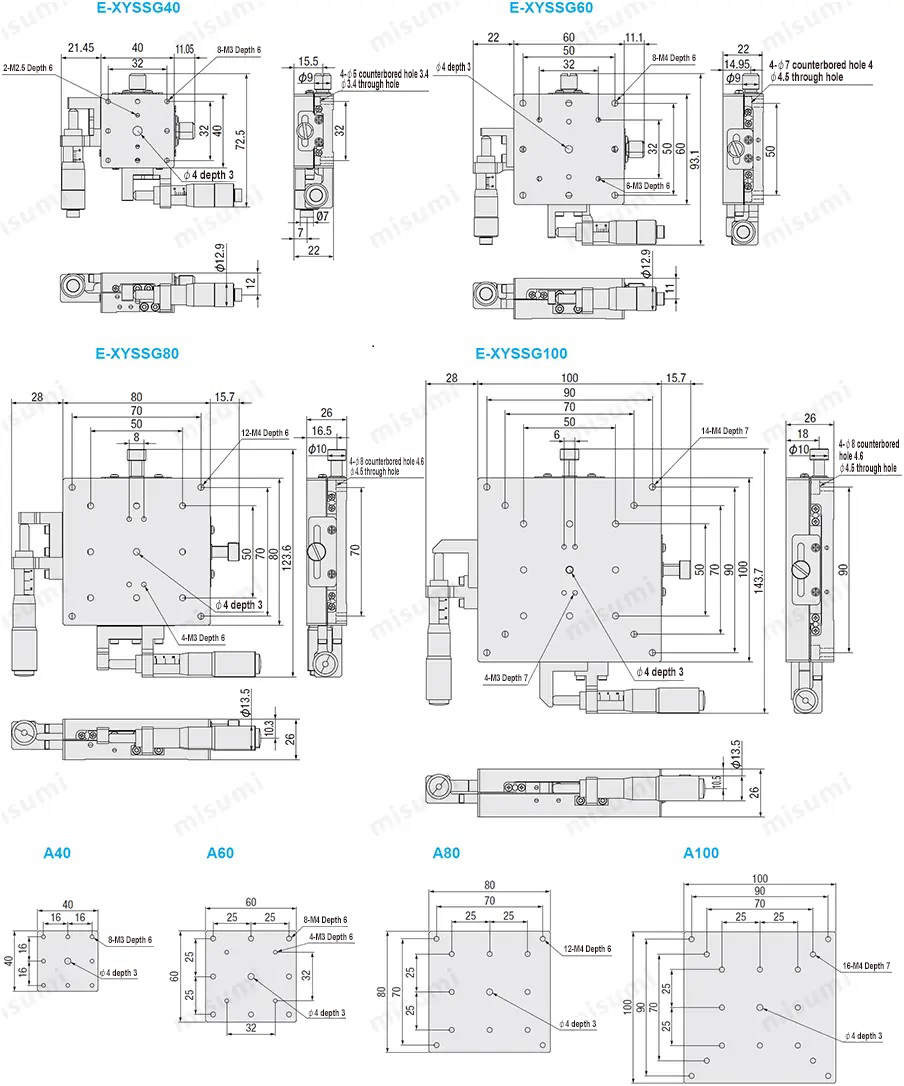
*A40, A60, A80, A100 are available sizes of the screw hole on sliding table
| Part Number | Positioning Stage Face (mm) | Movement (mm) | Load Capacity (N) | Straightness (μm) | Minimum Reading (μm) | Weight (kg) | |
| Type | No. | Horizontal | |||||
| E-XYSSG | 40 | 40×40 | ±6.5 | 88 | Within 10 | 10 | 0.34 |
| 60 | 60×60 | 186 | 0.64 | ||||
| 80 | 80×80 | ±12.5 | 196 | 1.32 | |||
| 100 | 100×100 | 245 | 2 | ||||
■Alteration
| Alterations | Changing the position of the micrometer knob | |||
| Spec. | Center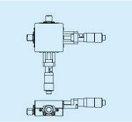 | Side Left and Right Reverse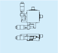 | Without Micrometer Rotation | |
| Code | A | CR | MN | |
Part Number
CAD Data download and 3D preview are not available because the part number has not yet been determined.
- *In order to open the CAD Data download and 3D preview screen, the part number must be fixed.
- Please confirm the part number from "Specification / Dimension"on the left side, and then perform the CAD Data Download / 3D Preview operation.
| Part Number |
|---|
| E-XYSSG40 |
| E-XYSSG40-A |
| E-XYSSG40-CR |
| E-XYSSG40-MN |
| E-XYSSG60 |
| E-XYSSG60-A |
| E-XYSSG60-CR |
| E-XYSSG60-MN |
| E-XYSSG80 |
| E-XYSSG80-A |
| E-XYSSG80-CR |
| E-XYSSG80-MN |
| E-XYSSG100 |
| E-XYSSG100-A |
| E-XYSSG100-CR |
| E-XYSSG100-MN |
| Part Number | Minimum order quantity | Volume Discount | Days to Ship | Table Dimensions | Alteration |
|---|---|---|---|---|---|
| 1 Piece(s) | Available | 10 Day(s) | 40 | Standard Type | |
| 1 Piece(s) | Available | 10 Day(s) | 40 | A | |
| 1 Piece(s) | Available | 10 Day(s) | 40 | CR | |
| 1 Piece(s) | Available | 10 Day(s) | 40 | MN | |
| 1 Piece(s) | Available | 10 Day(s) | 60 | Standard Type | |
| 1 Piece(s) | Available | 10 Day(s) | 60 | A | |
| 1 Piece(s) | Available | 10 Day(s) | 60 | CR | |
| 1 Piece(s) | Available | 10 Day(s) | 60 | MN | |
| 1 Piece(s) | Available | 10 Day(s) | 80 | Standard Type | |
| 1 Piece(s) | Available | 10 Day(s) | 80 | A | |
| 1 Piece(s) | Available | 10 Day(s) | 80 | CR | |
| 1 Piece(s) | Available | 10 Day(s) | 80 | MN | |
| 1 Piece(s) | Available | 10 Day(s) | 100 | Standard Type | |
| 1 Piece(s) | Available | 10 Day(s) | 100 | A | |
| 1 Piece(s) | Available | 10 Day(s) | 100 | CR | |
| 1 Piece(s) | Available | 10 Day(s) | 100 | MN |
Loading...
Feature 2: Low price is achieved by simplifying the structure and improving the machining process.
Feature 3: A wide range of alterations are available to enable installation and operation under different conditions.
Feature 4: By improving the clamping mechanism, the holding force of the positioning stage is greater than that of the standard type clamping mechanism.
| Type |  Material Material |  Surface Treatment Surface Treatment | Movement (mm) | Load Capacity (N) | Straightness |
| E-XYSSG | D2 Tool Steel | Chemically Nickel Plating | ±6.5~±12.5 | 88~245 | Within 10 μm |
■Amount of travel
The catalog drawing size is the state of travel 0mm, and taking this as reference, the distance moved in the left and right directions is the amount of travel.
■Load capacity
is the force in N that the positioning stage can withstand when the center of gravity of the workpiece is in the center of the positioning stage. If used in excess of the load capacity, the positioning stage may not move properly or get stuck. Refer to the values of "Horizontal" and "Vertical" for the load resistance for horizontal and vertical installation respectively. Note that when the linear motion positioning stage is installed vertically or upside down, the accuracy may be less than the value indicated in the catalog.
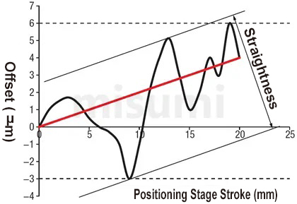
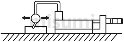
■Straightness
The maximum offset relative to the ideal axis of movement (the line connecting the start and end points is shown as the red line in the figure below. The black line is the actual trajectory of movement.) when the positioning stage moves at full stroke. Detection method: Place the micrometer on the positioning stage, with the pointer held against the reference block, let the positioning stage move at full stroke, and measure its maximum displacement, which is the straightness.
Usage Method
When mounting the positioning stage to the base, basically it is mounted by moving the positioning stage surface. Refer to the following diagram.
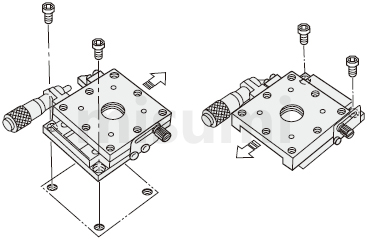
 The above diagram is for demonstration purpose only. Refer to each catalog or 3D data for detailed shapes and specifications of the positioning stage.
■Mounting Posture
| Diagram | 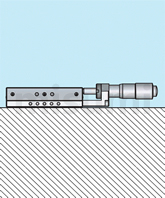 | 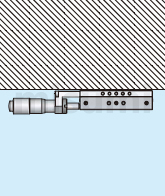 | 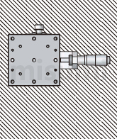 | 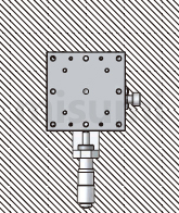 |
| Mounting Posture | Horizontal | Inverted | Side-Mounted Horizontal | Side-Mounted Vertical |
| Load Resistance Characteristics | ○ | ○ | △ | △ |
Horizontal, inverted, side-mounted horizontal or side-mounted vertical installation options are available. Other installation methods should be given more attention.Load capacity and accuracy will change greatly depending on the mounting posture.○:Same as horizontal load capacity.△:About 1/3 of the horizontal load capacity is the approximate standard, if the catalog contains the vertical load capacity, it should be given priority.■Vertical Use of X-Axis Positioning Stage
When using the X-axis positioning stage vertically, pay attention to the feed direction, which should not be in the same direction as gravity.
When using a micrometer knob type positioning stage, note that the positioning stage is reset by extension spring. If the force applied is greater than the spring load, the positioning stage surface may fall. For such occasions, alterations can be used as a solution.
| Wrong Usage Method | Correct Usage Method |
| (Usually) If the force applied exceeds the tensile load of the spring, the positioning stage surface may slip off because it cannot support the weight. | After selecting the alteration of the micrometer knob position change, the positioning stage surface does not fall even when used vertically. |
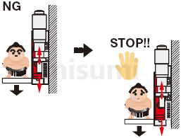 | 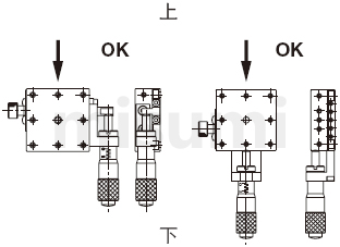 |
Avoid applying loads that exceed the load carrying range in the vertical direction.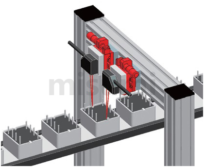
Example of Use
| Electronics/Home Appliance | Automotive | Medical | ||
 |  |  | ||
| Smart Phones | Semiconductor | Lithium battery | ||
 | 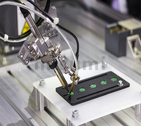 |  |
Recommended operating environment: 10~50℃, 20~70%RH (no condensation)
Accuracy assurance environment: 22±5℃, 20~70%RH (no condensation)
■Guiding mechanism
This positioning stage adopts crossed roller guide as the guiding mechanism. Please refill the lubricant at the right time according to the usage conditions to prevent the life of crossed roller guide from being shortened due to the decrease of lubricant and aging.
■Clamping mechanism
①The clamping mechanism of the positioning stage is fixed by the frictional force generated by the fastening screw, so when the applied external force exceeds the frictional force of the clamping mechanism section, it will cause the positioning stage to move. The user should take appropriate measures to avoid movement of the positioning stage surface during use. If clamping reinforcement is required, disc clamping or opposite clamping can be selected.
②The holding force is the value of the force that keeps the positioning stage surface from moving in the clamped condition. Since the maximum holding force varies with the tightening torque, please ensure a sufficiently large safety factor when designing.
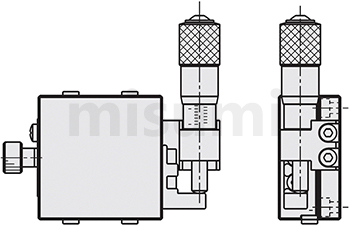
■Feed mechanism
The shape of a positioning stage with a micrometer knob installed as shown in the figure below is generally called the standard type. Free selection is possible by combining the installation space, mounting posture, and operation method. However, due to the structure of the product, there are some models where the installation position of the micrometer knob cannot be changed. For details, refer to the [Alteration] at the bottom of each product page.
■Flatness of the mounting surface
The upper and lower positioning stage surface may be deformed due to the different flatness of its mounting surface. Deformation of the positioning stage surface may result in gaps, looseness due to failure to obtain the specified preload, or poor sliding due to excessive preload. Therefore, it is recommended that the flatness of the mounting surface be kept at about 5 microns.
| X-Axis Motorized Positioning Stages | XY-Axis Motorized Positioning Stages | Z-Axis Motorized Positioning Stages | ||
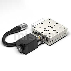 | 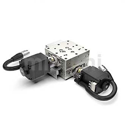 | 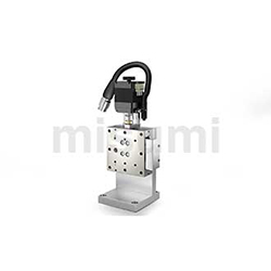 | ||
| Typical Model: C-XMBS420-L-A-2 | Typical Model: C-XYMBS420-L-A-2 | Typical Model: C-ZMBS420-L-A-2 | ||
| Advantages: low price, fast delivery | Advantages: low price, fast delivery | Advantages: low price, fast delivery |
- The specifications and dimensions of some parts may not be fully covered. For exact details, refer to manufacturer catalogs .
Tech Support
-
Credit Card
Kartu Kredit
-
Bank TransferTransfer Bank
MISUMI Contact
MISUMI Kontak
Copyright © MISUMI Corporation All Rights Reserved.
How can we improve?Bagaimana Kami bisa meningkatkan Pelayanan?
How can we improve?Bagaimana Kami bisa meningkatkan Pelayanan?
While we are not able to respond directly to comments submitted in this form, the information will be reviewed for future improvement.
Customer Privacy Policy Walaupun Kami tidak dapat langsung menjawab saran yang ditulis di lembar ini, informasinya akan kami review untuk peningkatan pelayanan dikemudian hari
Kebijakan Privacy
Thank you for your cooperation.Terima kasih atas kerjasama anda.
While we are not able to respond directly to comments submitted in this form, the information will be reviewed for future improvement.
Please use the inquiry form.
Customer Privacy Policy Walaupun Kami tidak dapat langsung menjawab saran yang ditulis di lembar ini, informasinya akan kami review untuk peningkatan pelayanan dikemudian hari
Silahkan pergunakan Forms Permintaan.
Kebijakan Privacy