(!)Due to Microsoft's end of support for Internet Explorer 11 on 15/06/2022, this site does not support the recommended environment.
63,000 Stock items for Same Day Shipping
63,000 Item Stok untuk Pengiriman di Hari yang Sama
Search by Category / Brand
Pencarian dengan
Kategori / Merek
Search by Category Pencarian dengan Kategori
- Automation Components
A wide variety of standard and configurable components for factory automation engineers in industries such as automotive, semiconductor, packaging, medical and many more.
- Linear Motion
- Rotary Motion
- Connecting Parts
- Rotary Power Transmission
- Motors
- Conveyors & Material Handling
- Locating, Positioning, Jigs & Fixtures
- Inspection
- Sensors, Switches
- Pneumatics, Hydraulics
- Vacuum Components
- Hydraulic Equipment
- Discharging / Painting Devices
- Pipe, Tubes, Hoses & Fittings
- Modules, Units
- Heaters, Temperature Control
- Framing & Support
- Casters, Leveling Mounts, Posts
- Doors, Cabinet Hardware
- Springs, Shock Absorbers
- Adjusting, Fastening, Magnets
- Antivibration, Soundproofing Materials, Safety Products
- Fasteners
A good selection of accessories such as screws, bolts, washers and nuts that you may need for your daily engineering usage.
- Materials
Browse industrial materials ranging from heat insulating plates, sponges, to metal and plastic materials in different sizes to meet your various applications.
- Wiring Components
A wide variety of wiring parts for connecting and protecting control and PC parts including Connectors, Cables, Electric Wires, Crimping Terminals and more.
- LAN Cables / Industrial Network Cables
- Cables by Application
- Cables with Connectors
- RS232 / Personal Computers / AV Cables
- Wires/Cables
- Connectors (General Purpose)
- Crimp Terminals
- Zip Ties
- Cable Glands
- Cable Bushings/Clips/Stickers
- Screws/Spacers
- Cable Accessories
- Tubes
- Protection Tubes
- Ducts/Wiremolds
- General Purpose Tools
- Dedicated Tools
- Soldering Supplies
- Electrical & Controls
A wide variety of controls and PC parts for electrical engineers including Controls, Powers, PC parts and more.
- Cutting Tools
A wide variety of cutting tools for many uses and work materials including End Mills, Drills, Cutters, Reamers, Turning Tools and more.
- Carbide End Mills
- HSS End Mills
- Milling Cutter Inserts/Holders
- Customized Straight Blade End Mills
- Dedicated Cutters
- Turning Tools
- Drill Bits
- Screw-Hole-Related Tools
- Reamers
- Chamfering / Centering Tools
- Fixtures Related to Cutting Tools
- Step Drills
- Hole Saws
- Clean Key Cutters
- Core Drills (Tip Tools)
- Magnetic Drilling Machine Cutters
- Drill Bits for Electric Drilling Machines
- Woodworking Drill Cutters
- Drills for Concrete
- Processing Tools
A wide variety of tools and supplies used in processing including Machine Tools, Measurement Tools, Grinding and Polishing Supplies and more.
- Material Handling & Storage
A wide variety of goods used in shipment, material handling and warehouse including Tape supplies, Stretch film, Truck, Shelf, Crane and more.
- Tape Supplies
- Cushioning Materials
- Stretch Films
- Cardboard
- Plastic Bags
- PP Bands
- Magic Tapes / Tying Belts
- Rubber Bands
- Strings/Ropes
- Cable Ties
- Tags
- Labelers
- Unpacking Cutters
- Packing Support Equipment
- Cloth Sheets for Packing
- Conveyance/Dolly Carts
- Tool Wagons
- Tool Cabinets / Container Racks
- Lifters / Hand Pallets
- Container Pallets
- Storage Supplies
- Shelves/Racks
- Work Benches
- Suspended Clamps/Suspended Belts
- Jack Winches
- Chain Block Cranes
- Bottles/Containers
- Bicycle Storage Area
- Safety & General Supplies
A large variety of goods for every kind of factories and offices including Protection items, Cleaning supplies, sanitations, office supplies and more.
- Lab & Clean Room Supplies
A large variety of items used in R&D and Clean Room including research Equipment, Laboratory Essentials, Analysis Supplies, Clean Environment-Related Equipment and more.
- Press Die Components
Choose from thousands of standard stamping die components including Punch & Die, Gas Springs, Guide Components, Coil Springs and many more.
- Plastic Mold Components
Browse our wide variety of mold components including Ejector Pins, Sleeves, Leader Components, Sprue Bushings and many more.
- Ejector Pins
- Sleeves, Center Pins
- Core Pins
- Sprue bushings, Gates, and other components
- Date Mark Inserts, Recycle Mark Inserts, Pins with Gas Vent
- Undercut, Plates
- Leader Components, Components for Ejector Space
- Mold Opening Controllers
- Cooling or Heating Components
- Accessories, Others
- Components of Large Mold, Die Casting
- Injection Molding Components
Browse our injection molding components including Heating Items, Couplers, Hoses and more.
- Injection Molding Machine Products
- Accessories of Equipment
- Auxiliary Equipment
- Air Nippers
- Air Cylinders
- Air Chuck for Runner
- Chuck Board Components
- Frames
- Suction Components
- Parallel Air Chuck
- Special Air Chuck
- Chemical for Injection Molding
- Mold Maintenance
- Heating Items
- Heat Insulation Sheets
- Couplers, Plugs, One-touch Joints
- Tubes, Hoses, Peripheral Components
- Komponen Mekanis
- Linear Motion
- Rotary Motion
- Connecting Parts
- Rotary Power Transmission
- Motors
- Conveyors & Material Handling
- Locating, Positioning, Jigs & Fixtures
- Inspection
- Sensors, Switches
- Pneumatics, Hydraulics
- Vacuum Components
- Hydraulic Equipment
- Discharging / Painting Devices
- Pipe, Tubes, Hoses & Fittings
- Modules, Units
- Heaters, Temperature Control
- Framing & Support
- Casters, Leveling Mounts, Posts
- Doors, Cabinet Hardware
- Springs, Shock Absorbers
- Adjusting, Fastening, Magnets
- Antivibration, Soundproofing Materials, Safety Products
- Sekrup, Baut, Washer, Nut
- Material
- Komponen Kabel
- LAN Cables / Industrial Network Cables
- Cables by Application
- Cables with Connectors
- RS232 / Personal Computers / AV Cables
- Wires/Cables
- Connectors (General Purpose)
- Crimp Terminals
- Zip Ties
- Cable Glands
- Cable Bushings/Clips/Stickers
- Screws/Spacers
- Cable Accessories
- Tubes
- Protection Tubes
- Ducts/Wiremolds
- General Purpose Tools
- Dedicated Tools
- Soldering Supplies
- Elektrikal & Kontrol
- Peralatan Pemotong
- Carbide End Mills
- HSS End Mills
- Milling Cutter Inserts/Holders
- Customized Straight Blade End Mills
- Dedicated Cutters
- Turning Tools
- Drill Bits
- Screw-Hole-Related Tools
- Reamers
- Chamfering / Centering Tools
- Fixtures Related to Cutting Tools
- Step Drills
- Hole Saws
- Clean Key Cutters
- Core Drills (Tip Tools)
- Magnetic Drilling Machine Cutters
- Drill Bits for Electric Drilling Machines
- Woodworking Drill Cutters
- Drills for Concrete
- Peralatan Produksi
- Penanganan Material & Penyimpanan
- Tape Supplies
- Cushioning Materials
- Stretch Films
- Cardboard
- Plastic Bags
- PP Bands
- Magic Tapes / Tying Belts
- Rubber Bands
- Strings/Ropes
- Cable Ties
- Tags
- Labelers
- Unpacking Cutters
- Packing Support Equipment
- Cloth Sheets for Packing
- Conveyance/Dolly Carts
- Tool Wagons
- Tool Cabinets / Container Racks
- Lifters / Hand Pallets
- Container Pallets
- Storage Supplies
- Shelves/Racks
- Work Benches
- Suspended Clamps/Suspended Belts
- Jack Winches
- Chain Block Cranes
- Bottles/Containers
- Bicycle Storage Area
- Perlengkapan Keamanan & Umum
- Perlengkapan Sanitasi & Lab
- Komponen Press Die
- Komponen Plastik Mold
- Ejector Pins
- Sleeves, Center Pins
- Core Pins
- Sprue bushings, Gates, and other components
- Date Mark Inserts, Recycle Mark Inserts, Pins with Gas Vent
- Undercut, Plates
- Leader Components, Components for Ejector Space
- Mold Opening Controllers
- Cooling or Heating Components
- Accessories, Others
- Components of Large Mold, Die Casting
- Komponen Injeksi Moulding
- Injection Molding Machine Products
- Accessories of Equipment
- Auxiliary Equipment
- Air Nippers
- Air Cylinders
- Air Chuck for Runner
- Chuck Board Components
- Frames
- Suction Components
- Parallel Air Chuck
- Special Air Chuck
- Chemical for Injection Molding
- Mold Maintenance
- Heating Items
- Heat Insulation Sheets
- Couplers, Plugs, One-touch Joints
- Tubes, Hoses, Peripheral Components
Search by Brand Pencarian dengan Merek


This translation is a Google translation Terjemahan ini adalah terjemahan Google
- Sehubungan dengan adanya Peraturan Baru Kementerian Perdagangan No.36 Tahun 2023 tentang Pembatasan Impor Barang, MISUMI Indonesia melakukan tindakan pencegahan. Lihat informasi detailnya di sini
Due to New Regulation of Ministry Of Trade No.36 of 2023 concerning retrictions on imports of goods, MISUMI Indonesia do precautions measure. See detail information here - Nomor telepon alternatif Kontak Layanan Pelanggan : 021-29182911| 021-29182991 | 021-29182997 | 021-29182998
Alternative telephone number Contact Customer Service: 021-29182911 | 021-29182991 | 021-29182997 | 021-29182998
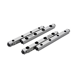
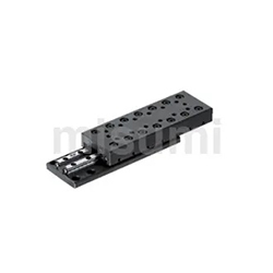
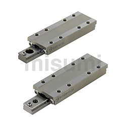
Cross Roller Guides
Click this image to zoom it.
Move the mouse over the image to zoom
- Volume Discount
Part Number
Configured Part Number is shown.
Feature 2: The contact area between the rolling element and the rail surface is large, and the elastic deformation is small. In addition, there are many effective rolling elements, which can achieve high rigidity and high load movement.
Feature 3: Flexible structural design, easy installation and use, and long service life.
Feature 4: Low mechanical energy consumption, high accuracy, fast speed, and large load-bearing capacity.
| Type |  Material Material |  Hardness Hardness | Heat resistant temperature |
E-CRV | Bearing Steel | 60HRC~ | -20℃~110℃ |
E-CRVS | Stainless Steel | 58HRC~ | -20℃~140℃ |
 1 set include 4 rails and 2 retainers
| Series | Part Number | Stroke (Round Trip) | L | M×P | Roller Quantity | Basic Rated Load | ||
| Type | No. | C (Dynamic) N | Co (Static) N | |||||
| V1 | E-CRV (Bearing Steel) E-CRVS (Stainless Steel) | 1020 | 12 | 20 | 1×10 | 5 | 490 | 345 |
| 1030 | 22 | 30 | 2×10 | 7 | 686 | 483 | ||
| 1040 | 27 | 40 | 3×10 | 10 | 980 | 690 | ||
| 1050 | 32 | 50 | 4×10 | 13 | 1274 | 897 | ||
| 1060 | 37 | 60 | 5×10 | 16 | 1568 | 1104 | ||
| 1070 | 42 | 70 | 6×10 | 19 | 1862 | 1311 | ||
| 1080 | 52 | 80 | 7×10 | 21 | 2058 | 1449 | ||
| V2 | 2030 | 18 | 30 | 1×15 | 5 | 880 | 635 | |
| 2045 | 24 | 45 | 2×15 | 8 | 1408 | 1016 | ||
| 2060 | 30 | 60 | 3×15 | 11 | 1936 | 1397 | ||
| 2075 | 44 | 75 | 4×15 | 13 | 2288 | 1651 | ||
| 2090 | 50 | 90 | 5×15 | 16 | 2816 | 2032 | ||
| 20105 | 64 | 105 | 6×15 | 18 | 3168 | 2286 | ||
| 20120 | 70 | 120 | 7×15 | 21 | 3696 | 2667 | ||
| 20135 | 84 | 135 | 8×15 | 23 | 4048 | 2921 | ||
| 20150 | 90 | 150 | 9×15 | 26 | 4576 | 3302 | ||
| 20165 | 96 | 165 | 10×15 | 29 | 5104 | 3683 | ||
| 20180 | 102 | 180 | 11×15 | 32 | 5632 | 4064 | ||
| V3 | 3050 | 28 | 50 | 1×25 | 7 | 2541 | 1925 | |
| 3075 | 48 | 75 | 2×25 | 10 | 3630 | 2750 | ||
| 30100 | 58 | 100 | 3×25 | 14 | 5082 | 3850 | ||
| 30125 | 78 | 125 | 4×25 | 17 | 6171 | 4675 | ||
| 30150 | 88 | 150 | 5×25 | 21 | 7623 | 5775 | ||
| 30175 | 108 | 175 | 6×25 | 24 | 8712 | 6600 | ||
| 30200 | 118 | 200 | 7×25 | 28 | 10164 | 7700 | ||
| 30225 | 138 | 225 | 8×25 | 31 | 11253 | 8525 | ||
| 30250 | 148 | 250 | 9×25 | 35 | 12705 | 9625 | ||
| V4 | 4080 | 58 | 80 | 1×40 | 7 | 5348 | 4459 | |
| 40120 | 82 | 120 | 2×40 | 11 | 8404 | 7007 | ||
| 40160 | 106 | 160 | 3×40 | 15 | 11460 | 9555 | ||
| 40200 | 130 | 200 | 4×40 | 19 | 14516 | 12103 | ||
| 40240 | 154 | 240 | 5×40 | 23 | 17572 | 14651 | ||
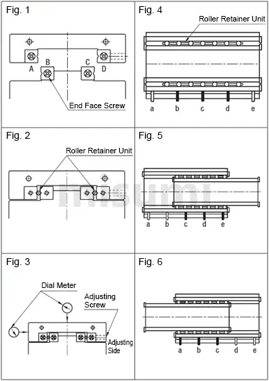
①Secure slide rails A, B and C to the positioning stage and the table with bolts, and slightly tighten the slide rail D. (Figure 1)
②Remove the end stop and insert the cage from the ends. (Figure 2)
③Move the positioning stage side to side to position the cage in the center of the rail.
④Install the dial indicator in the specified position. (Figure 3)
⑤Drive the positioning stage, and tighten the adjusting screws a to e in the range of the cage with a torque wrench or other tool. (Figures 4 to 6)
⑥Before the value of the dial indicator reaches its minimum and does not change, conduct the operation in step 5.
⑦When the value of the dial indicator is at the minimum and does not change,completely tighten the adjusting screws.
⑧Slightly tighten the slide rail D before the final fixation.
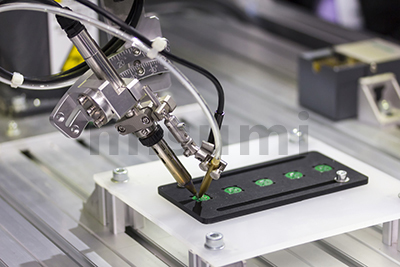
 The left image shows the MISUMI CRU series cross roller positioning stage Click
 here
here| Electronics/Home Appliance | Automotive | |
 |  | |
| Smart Phones | Semiconductor | |
 |  |
②Please be careful when using the roller retainer unit until it has been properly fixed and securely installed to prevent the roller from falling off.
③The screw on the slide rail end face only plays the role of preventing the retainer from falling off and cannot be used as a limit mechanism. If you need a limit function, please design a dedicated limit mechanism.
④Principles for paired use of the entire set
The accuracy of the slide rails is accurately controlled on a set by set basis, and mixing different sets of slide rails may cause changes in accuracy. Please pay full attention when assembling.
⑤Prevent retainer offset
When used at half stroke or high speed, the retainer may shift due to inertial forces when the slide stops. As a countermeasure against retainer offset, it is recommended to move several times over full stroke during use and set the retainer in the center position of the slide rail.
⑥Please apply lubricating grease according to the actual usage conditions and environment in a timely manner
Usually, the grease filling interval is 6 months or 1000KM. For longer moving distance, 3 months, or when the moving distance exceeds 1000km within the time limit, the 1000km shall prevail. But this is only the grease filling interval according to the moving distance standard. Depending on the operating environment, the grease injection interval must be shortened appropriately when the grease is aging and dirty.

Part Number
CAD Data download and 3D preview are not available because the part number has not yet been determined.
- *In order to open the CAD Data download and 3D preview screen, the part number must be fixed.
- Please confirm the part number from "Specification / Dimension"on the left side, and then perform the CAD Data Download / 3D Preview operation.
| Part Number | Minimum order quantity | Volume Discount | Days to Ship | RoHS | Material | Series | Dimension L (mm) |
|---|---|---|---|---|---|---|---|
| 1 Piece(s) | Available | 10 Day(s) | - | Bearing steel | 1000 | 20 | |
| 1 Piece(s) | Available | 10 Day(s) | - | Bearing steel | 1000 | 30 | |
| 1 Piece(s) | Available | 10 Day(s) | - | Bearing steel | 1000 | 40 | |
| 1 Piece(s) | Available | 10 Day(s) | - | Bearing steel | 1000 | 50 | |
| 1 Piece(s) | Available | 10 Day(s) | - | Bearing steel | 1000 | 60 | |
| 1 Piece(s) | Available | 10 Day(s) | - | Bearing steel | 1000 | 70 | |
| 1 Piece(s) | Available | 10 Day(s) | - | Bearing steel | 1000 | 80 | |
| 1 Piece(s) | Available | 10 Day(s) | - | Bearing steel | 2000 | 105 | |
| 1 Piece(s) | Available | 10 Day(s) | - | Bearing steel | 2000 | 120 | |
| 1 Piece(s) | Available | 10 Day(s) | - | Bearing steel | 2000 | 135 | |
| 1 Piece(s) | Available | 10 Day(s) | - | Bearing steel | 2000 | 150 | |
| 1 Piece(s) | Available | 10 Day(s) | - | Bearing steel | 2000 | 165 | |
| 1 Piece(s) | Available | 10 Day(s) | - | Bearing steel | 2000 | 180 | |
| 1 Piece(s) | Available | 10 Day(s) | - | Bearing steel | 2000 | 30 | |
| 1 Piece(s) | Available | 10 Day(s) | - | Bearing steel | 2000 | 45 | |
| 1 Piece(s) | Available | Same day | - | Bearing steel | 2000 | 60 | |
| 1 Piece(s) | Available | 10 Day(s) | - | Bearing steel | 2000 | 75 | |
| 1 Piece(s) | Available | 10 Day(s) | - | Bearing steel | 2000 | 90 | |
| 1 Piece(s) | Available | 10 Day(s) | - | Bearing steel | 3000 | 100 | |
| 1 Piece(s) | Available | 10 Day(s) | - | Bearing steel | 3000 | 125 | |
| 1 Piece(s) | Available | 10 Day(s) | - | Bearing steel | 3000 | 150 | |
| 1 Piece(s) | Available | 10 Day(s) | - | Bearing steel | 3000 | 175 | |
| 1 Piece(s) | Available | 10 Day(s) | - | Bearing steel | 3000 | 200 | |
| 1 Piece(s) | Available | 10 Day(s) | - | Bearing steel | 3000 | 225 | |
| 1 Piece(s) | Available | 10 Day(s) | - | Bearing steel | 3000 | 250 | |
| 1 Piece(s) | Available | 10 Day(s) | - | Bearing steel | 3000 | 50 | |
| 1 Piece(s) | Available | 10 Day(s) | - | Bearing steel | 3000 | 75 | |
| 1 Piece(s) | Available | 10 Day(s) | - | Bearing steel | 4000 | 120 | |
| 1 Piece(s) | Available | 10 Day(s) | - | Bearing steel | 4000 | 160 | |
| 1 Piece(s) | Available | 10 Day(s) | - | Bearing steel | 4000 | 200 | |
| 1 Piece(s) | Available | 10 Day(s) | - | Bearing steel | 4000 | 240 | |
| 1 Piece(s) | Available | 10 Day(s) | - | Bearing steel | 4000 | 80 | |
| 1 Piece(s) | Available | 10 Day(s) | 10 | Stainless steel | 1000 | 20 | |
| 1 Piece(s) | Available | 10 Day(s) | 10 | Stainless steel | 1000 | 30 | |
| 1 Piece(s) | Available | 10 Day(s) | 10 | Stainless steel | 1000 | 40 | |
| 1 Piece(s) | Available | 10 Day(s) | 10 | Stainless steel | 1000 | 50 | |
| 1 Piece(s) | Available | 10 Day(s) | 10 | Stainless steel | 1000 | 60 | |
| 1 Piece(s) | Available | 10 Day(s) | 10 | Stainless steel | 1000 | 70 | |
| 1 Piece(s) | Available | 10 Day(s) | 10 | Stainless steel | 1000 | 80 | |
| 1 Piece(s) | Available | 10 Day(s) | 10 | Stainless steel | 2000 | 105 | |
| 1 Piece(s) | Available | 10 Day(s) | 10 | Stainless steel | 2000 | 120 | |
| 1 Piece(s) | Available | 10 Day(s) | 10 | Stainless steel | 2000 | 135 | |
| 1 Piece(s) | Available | 10 Day(s) | 10 | Stainless steel | 2000 | 150 | |
| 1 Piece(s) | Available | 10 Day(s) | 10 | Stainless steel | 2000 | 165 | |
| 1 Piece(s) | Available | 10 Day(s) | 10 | Stainless steel | 2000 | 180 | |
| 1 Piece(s) | Available | 10 Day(s) | 10 | Stainless steel | 2000 | 30 | |
| 1 Piece(s) | Available | 10 Day(s) | 10 | Stainless steel | 2000 | 45 | |
| 1 Piece(s) | Available | 10 Day(s) | 10 | Stainless steel | 2000 | 60 | |
| 1 Piece(s) | Available | 10 Day(s) | 10 | Stainless steel | 2000 | 75 | |
| 1 Piece(s) | Available | 10 Day(s) | 10 | Stainless steel | 2000 | 90 | |
| 1 Piece(s) | Available | 10 Day(s) | 10 | Stainless steel | 3000 | 100 | |
| 1 Piece(s) | Available | 10 Day(s) | 10 | Stainless steel | 3000 | 125 | |
| 1 Piece(s) | Available | 10 Day(s) | 10 | Stainless steel | 3000 | 150 | |
| 1 Piece(s) | Available | 10 Day(s) | 10 | Stainless steel | 3000 | 175 | |
| 1 Piece(s) | Available | 10 Day(s) | 10 | Stainless steel | 3000 | 200 | |
| 1 Piece(s) | Available | 10 Day(s) | 10 | Stainless steel | 3000 | 225 | |
| 1 Piece(s) | Available | 10 Day(s) | 10 | Stainless steel | 3000 | 250 | |
| 1 Piece(s) | Available | 10 Day(s) | 10 | Stainless steel | 3000 | 50 | |
| 1 Piece(s) | Available | 10 Day(s) | 10 | Stainless steel | 3000 | 75 | |
| 1 Piece(s) | Available | 10 Day(s) | 10 | Stainless steel | 4000 | 120 |
Loading...
| Type | Material | Hardness | Heat resistant temperature |
E-CRV | Bearing Steel | 60HRC~ | -20℃~110℃ |
E-CRVS | Stainless Steel | 58HRC~ | -20℃~140℃ |
1 set include 4 rails and 2 retainers| Series | Part Number | Stroke (Round Trip) | L | M×P | Roller Quantity | Basic Rated Load | ||
| Type | No. | C (Dynamic) N | Co (Static) N | |||||
| V1 | E-CRV (Bearing Steel) E-CRVS (Stainless Steel) | 1020 | 12 | 20 | 1×10 | 5 | 490 | 345 |
| 1030 | 22 | 30 | 2×10 | 7 | 686 | 483 | ||
| 1040 | 27 | 40 | 3×10 | 10 | 980 | 690 | ||
| 1050 | 32 | 50 | 4×10 | 13 | 1274 | 897 | ||
| 1060 | 37 | 60 | 5×10 | 16 | 1568 | 1104 | ||
| 1070 | 42 | 70 | 6×10 | 19 | 1862 | 1311 | ||
| 1080 | 52 | 80 | 7×10 | 21 | 2058 | 1449 | ||
| V2 | 2030 | 18 | 30 | 1×15 | 5 | 880 | 635 | |
| 2045 | 24 | 45 | 2×15 | 8 | 1408 | 1016 | ||
| 2060 | 30 | 60 | 3×15 | 11 | 1936 | 1397 | ||
| 2075 | 44 | 75 | 4×15 | 13 | 2288 | 1651 | ||
| 2090 | 50 | 90 | 5×15 | 16 | 2816 | 2032 | ||
| 20105 | 64 | 105 | 6×15 | 18 | 3168 | 2286 | ||
| 20120 | 70 | 120 | 7×15 | 21 | 3696 | 2667 | ||
| 20135 | 84 | 135 | 8×15 | 23 | 4048 | 2921 | ||
| 20150 | 90 | 150 | 9×15 | 26 | 4576 | 3302 | ||
| 20165 | 96 | 165 | 10×15 | 29 | 5104 | 3683 | ||
| 20180 | 102 | 180 | 11×15 | 32 | 5632 | 4064 | ||
| V3 | 3050 | 28 | 50 | 1×25 | 7 | 2541 | 1925 | |
| 3075 | 48 | 75 | 2×25 | 10 | 3630 | 2750 | ||
| 30100 | 58 | 100 | 3×25 | 14 | 5082 | 3850 | ||
| 30125 | 78 | 125 | 4×25 | 17 | 6171 | 4675 | ||
| 30150 | 88 | 150 | 5×25 | 21 | 7623 | 5775 | ||
| 30175 | 108 | 175 | 6×25 | 24 | 8712 | 6600 | ||
| 30200 | 118 | 200 | 7×25 | 28 | 10164 | 7700 | ||
| 30225 | 138 | 225 | 8×25 | 31 | 11253 | 8525 | ||
| 30250 | 148 | 250 | 9×25 | 35 | 12705 | 9625 | ||
| V4 | 4080 | 58 | 80 | 1×40 | 7 | 5348 | 4459 | |
| 40120 | 82 | 120 | 2×40 | 11 | 8404 | 7007 | ||
| 40160 | 106 | 160 | 3×40 | 15 | 11460 | 9555 | ||
| 40200 | 130 | 200 | 4×40 | 19 | 14516 | 12103 | ||
| 40240 | 154 | 240 | 5×40 | 23 | 17572 | 14651 | ||
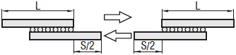
■Stroke
As shown in the figure below, the stroke is symmetrical on both sides, and the movement distance is only 1/2 of the stroke.
■Rated Load
The rated load of the cross roller guide is calculated with the table below.
| Load direction | 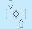 | ||
| Dynamic rated load (N) |  | ||
| Static rated load (N) |  | ||
| Load direction |  | ||
| Dynamic rated load (N) |  | ||
| Static rated load (N) |  | ||
| Load direction | 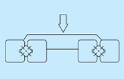 | ||
| Dynamic rated load (N) |  | ||
| Static rated load (N) |  | ||
CO1: Basic static rated load of each roller (N)
Z: Number of rolling elements
The life of cross roller guide is calculated with the formula below.

L: Operating Life (km) fT: Temperature coefficient (see Temperature Coefficient Table) C: Dynamic Load Rating (N)
fw: Load coefficient (see Load Coefficient Table) P: Acting load (N)
Life Time

Lh: Life Hours (hr) L: Operating Life (km)
ls: Stroke length (m) n1: Number of round trips per minute (cpm)
Description of relevant coefficients
● Load coefficient (fW)
When calculating the load acting on the cross roller positioning stage, it is necessary to correctly calculate the inertial force or torque load generated by the speed of the movement and its relationship to the change in time, etc., in addition to the weight of the object. However, it is difficult to attain accurate calculations due to potential vibration and impacts caused during reciprocating motion, other than repeat start-stop motion. Therefore, the load coefficients shown in the table can be used to simplify the operating life calculation.
Table: Load Coefficient
| Operating Conditions | fw | |
| No external impact vibration | 1.0~1.5 | |
| At low speed | 15m/min or less | |
| No obvious impact vibration | 1.5~2.0 | |
| At medium speed | 60m/min or less | |
| With external impact vibration | 2.0~3.5 | |
| At high speed | 60m/min or more | |
●Temperature coefficient (fT)
If the temperature of the cross roller positioning stage exceeds 100°C, the hardness of the positioning stage and the shaft will decrease, the allowable load will be lower than the load during use at room temperature, and the life will be shortened accordingly. Please use the temperature coefficient to compensate for the rated life.
Please use cross roller positioning stages within the heat-resistance temperature range indicated on each product page.
Figure: Temperature Coefficient
- The specifications and dimensions of some parts may not be fully covered. For exact details, refer to manufacturer catalogs .
Frequently asked question (FAQ)
- Question: What is retainer offset? How to prevent retainer offset?
- Answer: The offset of the guide rail disk is caused by the inertial force that occurs when the crossed roller guide rail stops during use at half stroke or high speed. As a countermeasure against retainer offset, it is recommended to move several times over full stroke during use and set the retainer in the center position of the slide rail.
- Question: Can the screw on the slide rail end face of the crossed roller guide serve as a limit screw?
- Answer: No, it cannot. The screw on the slide rail end face only plays the role of preventing the retainer from falling off and cannot be used as a limit mechanism. If you need a limit function, please design a dedicated limit mechanism.
- Question: Is it necessary to regularly apply grease to the crossed roller guide? What is the interval between applying grease?
- Answer: Yes, it is necessary. Grease can form an oil film on the surface of the roller surface and rolling surface to effectively reduce friction and prevent sintering. The recommended grease filling interval is usually every 6 months. For longer moving distance, 3 months, or when the moving distance exceeds 1000km within the time limit, the 1000km shall prevail. But this is only the grease filling interval according to the moving distance standard. Depending on the operating environment, the grease injection interval must be shortened appropriately when the grease is aging and dirty.
- Question: How to install the crossed roller guide?
- Answer: You can install the crossed roller guide referring to the [Installation Procedure of Crossed Roller Guide] on P.412 in the 2018 FA Catalog.
Tech Support
-
Credit Card
Kartu Kredit
-
Bank TransferTransfer Bank
MISUMI Contact
MISUMI Kontak
Copyright © MISUMI Corporation All Rights Reserved.
How can we improve?Bagaimana Kami bisa meningkatkan Pelayanan?
How can we improve?Bagaimana Kami bisa meningkatkan Pelayanan?
While we are not able to respond directly to comments submitted in this form, the information will be reviewed for future improvement.
Customer Privacy Policy Walaupun Kami tidak dapat langsung menjawab saran yang ditulis di lembar ini, informasinya akan kami review untuk peningkatan pelayanan dikemudian hari
Kebijakan Privacy
Thank you for your cooperation.Terima kasih atas kerjasama anda.
While we are not able to respond directly to comments submitted in this form, the information will be reviewed for future improvement.
Please use the inquiry form.
Customer Privacy Policy Walaupun Kami tidak dapat langsung menjawab saran yang ditulis di lembar ini, informasinya akan kami review untuk peningkatan pelayanan dikemudian hari
Silahkan pergunakan Forms Permintaan.
Kebijakan Privacy