(!)Due to Microsoft's end of support for Internet Explorer 11 on 15/06/2022, this site does not support the recommended environment.
63,000 Stock items for Same Day Shipping
63,000 Item Stok untuk Pengiriman di Hari yang Sama
Search by Category / Brand
Pencarian dengan
Kategori / Merek
Search by Category Pencarian dengan Kategori
- Automation Components
A wide variety of standard and configurable components for factory automation engineers in industries such as automotive, semiconductor, packaging, medical and many more.
- Linear Motion
- Rotary Motion
- Connecting Parts
- Rotary Power Transmission
- Motors
- Conveyors & Material Handling
- Locating, Positioning, Jigs & Fixtures
- Inspection
- Sensors, Switches
- Pneumatics, Hydraulics
- Vacuum Components
- Hydraulic Equipment
- Discharging / Painting Devices
- Pipe, Tubes, Hoses & Fittings
- Modules, Units
- Heaters, Temperature Control
- Framing & Support
- Casters, Leveling Mounts, Posts
- Doors, Cabinet Hardware
- Springs, Shock Absorbers
- Adjusting, Fastening, Magnets
- Antivibration, Soundproofing Materials, Safety Products
- Fasteners
A good selection of accessories such as screws, bolts, washers and nuts that you may need for your daily engineering usage.
- Materials
Browse industrial materials ranging from heat insulating plates, sponges, to metal and plastic materials in different sizes to meet your various applications.
- Wiring Components
A wide variety of wiring parts for connecting and protecting control and PC parts including Connectors, Cables, Electric Wires, Crimping Terminals and more.
- LAN Cables / Industrial Network Cables
- Cables by Application
- Cables with Connectors
- RS232 / Personal Computers / AV Cables
- Wires/Cables
- Connectors (General Purpose)
- Crimp Terminals
- Zip Ties
- Cable Glands
- Cable Bushings/Clips/Stickers
- Screws/Spacers
- Cable Accessories
- Tubes
- Protection Tubes
- Ducts/Wiremolds
- General Purpose Tools
- Dedicated Tools
- Soldering Supplies
- Electrical & Controls
A wide variety of controls and PC parts for electrical engineers including Controls, Powers, PC parts and more.
- Cutting Tools
A wide variety of cutting tools for many uses and work materials including End Mills, Drills, Cutters, Reamers, Turning Tools and more.
- Carbide End Mills
- HSS End Mills
- Milling Cutter Inserts/Holders
- Customized Straight Blade End Mills
- Dedicated Cutters
- Turning Tools
- Drill Bits
- Screw-Hole-Related Tools
- Reamers
- Chamfering / Centering Tools
- Fixtures Related to Cutting Tools
- Step Drills
- Hole Saws
- Clean Key Cutters
- Core Drills (Tip Tools)
- Magnetic Drilling Machine Cutters
- Drill Bits for Electric Drilling Machines
- Woodworking Drill Cutters
- Drills for Concrete
- Processing Tools
A wide variety of tools and supplies used in processing including Machine Tools, Measurement Tools, Grinding and Polishing Supplies and more.
- Material Handling & Storage
A wide variety of goods used in shipment, material handling and warehouse including Tape supplies, Stretch film, Truck, Shelf, Crane and more.
- Tape Supplies
- Cushioning Materials
- Stretch Films
- Cardboard
- Plastic Bags
- PP Bands
- Magic Tapes / Tying Belts
- Rubber Bands
- Strings/Ropes
- Cable Ties
- Tags
- Labelers
- Unpacking Cutters
- Packing Support Equipment
- Cloth Sheets for Packing
- Conveyance/Dolly Carts
- Tool Wagons
- Tool Cabinets / Container Racks
- Lifters / Hand Pallets
- Container Pallets
- Storage Supplies
- Shelves/Racks
- Work Benches
- Suspended Clamps/Suspended Belts
- Jack Winches
- Chain Block Cranes
- Bottles/Containers
- Bicycle Storage Area
- Safety & General Supplies
A large variety of goods for every kind of factories and offices including Protection items, Cleaning supplies, sanitations, office supplies and more.
- Lab & Clean Room Supplies
A large variety of items used in R&D and Clean Room including research Equipment, Laboratory Essentials, Analysis Supplies, Clean Environment-Related Equipment and more.
- Press Die Components
Choose from thousands of standard stamping die components including Punch & Die, Gas Springs, Guide Components, Coil Springs and many more.
- Plastic Mold Components
Browse our wide variety of mold components including Ejector Pins, Sleeves, Leader Components, Sprue Bushings and many more.
- Ejector Pins
- Sleeves, Center Pins
- Core Pins
- Sprue bushings, Gates, and other components
- Date Mark Inserts, Recycle Mark Inserts, Pins with Gas Vent
- Undercut, Plates
- Leader Components, Components for Ejector Space
- Mold Opening Controllers
- Cooling or Heating Components
- Accessories, Others
- Components of Large Mold, Die Casting
- Injection Molding Components
Browse our injection molding components including Heating Items, Couplers, Hoses and more.
- Injection Molding Machine Products
- Accessories of Equipment
- Auxiliary Equipment
- Air Nippers
- Air Cylinders
- Air Chuck for Runner
- Chuck Board Components
- Frames
- Suction Components
- Parallel Air Chuck
- Special Air Chuck
- Chemical for Injection Molding
- Mold Maintenance
- Heating Items
- Heat Insulation Sheets
- Couplers, Plugs, One-touch Joints
- Tubes, Hoses, Peripheral Components
- Komponen Mekanis
- Linear Motion
- Rotary Motion
- Connecting Parts
- Rotary Power Transmission
- Motors
- Conveyors & Material Handling
- Locating, Positioning, Jigs & Fixtures
- Inspection
- Sensors, Switches
- Pneumatics, Hydraulics
- Vacuum Components
- Hydraulic Equipment
- Discharging / Painting Devices
- Pipe, Tubes, Hoses & Fittings
- Modules, Units
- Heaters, Temperature Control
- Framing & Support
- Casters, Leveling Mounts, Posts
- Doors, Cabinet Hardware
- Springs, Shock Absorbers
- Adjusting, Fastening, Magnets
- Antivibration, Soundproofing Materials, Safety Products
- Sekrup, Baut, Washer, Nut
- Material
- Komponen Kabel
- LAN Cables / Industrial Network Cables
- Cables by Application
- Cables with Connectors
- RS232 / Personal Computers / AV Cables
- Wires/Cables
- Connectors (General Purpose)
- Crimp Terminals
- Zip Ties
- Cable Glands
- Cable Bushings/Clips/Stickers
- Screws/Spacers
- Cable Accessories
- Tubes
- Protection Tubes
- Ducts/Wiremolds
- General Purpose Tools
- Dedicated Tools
- Soldering Supplies
- Elektrikal & Kontrol
- Peralatan Pemotong
- Carbide End Mills
- HSS End Mills
- Milling Cutter Inserts/Holders
- Customized Straight Blade End Mills
- Dedicated Cutters
- Turning Tools
- Drill Bits
- Screw-Hole-Related Tools
- Reamers
- Chamfering / Centering Tools
- Fixtures Related to Cutting Tools
- Step Drills
- Hole Saws
- Clean Key Cutters
- Core Drills (Tip Tools)
- Magnetic Drilling Machine Cutters
- Drill Bits for Electric Drilling Machines
- Woodworking Drill Cutters
- Drills for Concrete
- Peralatan Produksi
- Penanganan Material & Penyimpanan
- Tape Supplies
- Cushioning Materials
- Stretch Films
- Cardboard
- Plastic Bags
- PP Bands
- Magic Tapes / Tying Belts
- Rubber Bands
- Strings/Ropes
- Cable Ties
- Tags
- Labelers
- Unpacking Cutters
- Packing Support Equipment
- Cloth Sheets for Packing
- Conveyance/Dolly Carts
- Tool Wagons
- Tool Cabinets / Container Racks
- Lifters / Hand Pallets
- Container Pallets
- Storage Supplies
- Shelves/Racks
- Work Benches
- Suspended Clamps/Suspended Belts
- Jack Winches
- Chain Block Cranes
- Bottles/Containers
- Bicycle Storage Area
- Perlengkapan Keamanan & Umum
- Perlengkapan Sanitasi & Lab
- Komponen Press Die
- Komponen Plastik Mold
- Ejector Pins
- Sleeves, Center Pins
- Core Pins
- Sprue bushings, Gates, and other components
- Date Mark Inserts, Recycle Mark Inserts, Pins with Gas Vent
- Undercut, Plates
- Leader Components, Components for Ejector Space
- Mold Opening Controllers
- Cooling or Heating Components
- Accessories, Others
- Components of Large Mold, Die Casting
- Komponen Injeksi Moulding
- Injection Molding Machine Products
- Accessories of Equipment
- Auxiliary Equipment
- Air Nippers
- Air Cylinders
- Air Chuck for Runner
- Chuck Board Components
- Frames
- Suction Components
- Parallel Air Chuck
- Special Air Chuck
- Chemical for Injection Molding
- Mold Maintenance
- Heating Items
- Heat Insulation Sheets
- Couplers, Plugs, One-touch Joints
- Tubes, Hoses, Peripheral Components
Search by Brand Pencarian dengan Merek


This translation is a Google translation Terjemahan ini adalah terjemahan Google
- Sehubungan dengan adanya Peraturan Baru Kementerian Perdagangan No.36 Tahun 2023 tentang Pembatasan Impor Barang, MISUMI Indonesia melakukan tindakan pencegahan. Lihat informasi detailnya di sini
Due to New Regulation of Ministry Of Trade No.36 of 2023 concerning retrictions on imports of goods, MISUMI Indonesia do precautions measure. See detail information here - Nomor telepon alternatif Kontak Layanan Pelanggan : 021-29182911| 021-29182991 | 021-29182997 | 021-29182998
Alternative telephone number Contact Customer Service: 021-29182911 | 021-29182991 | 021-29182997 | 021-29182998
Manual Goniometer Stages Dovetail Type Copper Material Double Axis


Part Number
Configured Part Number is shown.
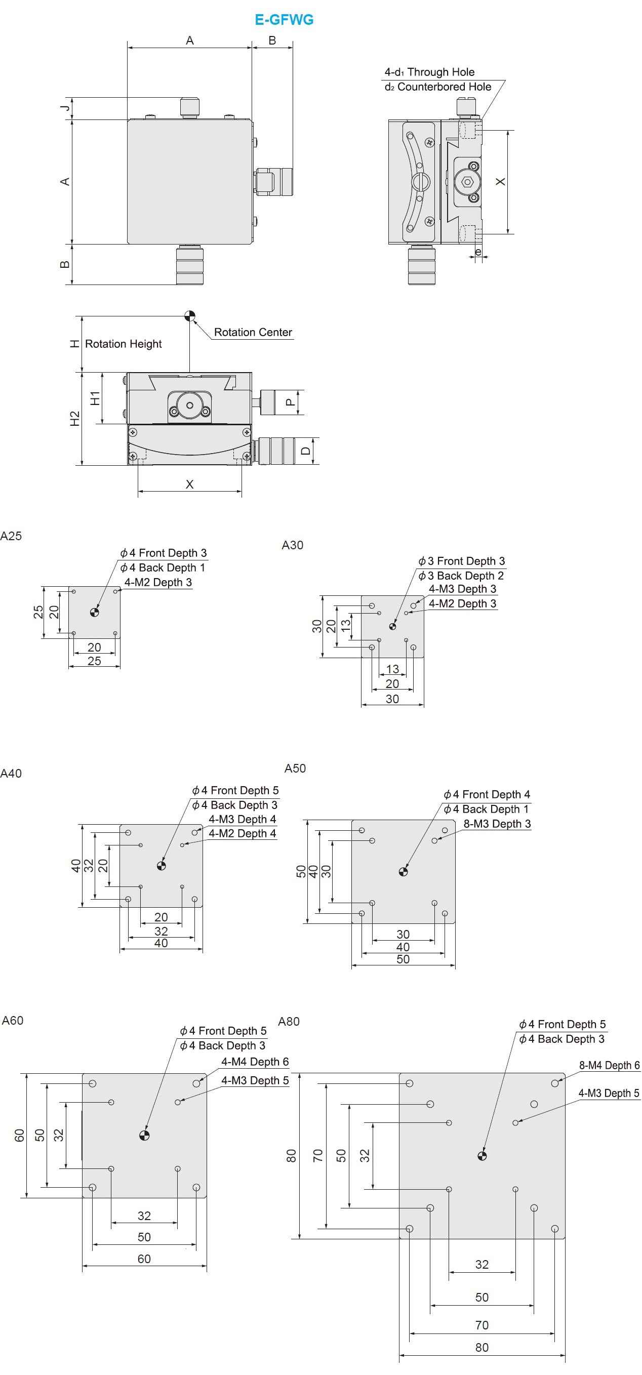
| Part Number | Top View | Main View | Side View | Stage Surface (MM) | Height of Rotation Center (mm) | Travel Distance | Travel Distance Per 1 Knob Rotation | Allowable Load Torque(N·m) | Load Capacity (N) | Weight (kg) | ||||||||||
| TYPE | A-H | B | J | H1 | H2 | D | P | e | d1 | d2 | X | Up and down swing | Left and right swing | Lateral rolling | ||||||
| E-GFWG | 25-20 | 16.5 | 8.4 | 15 | 30 | 8 | 8 | 4 | 2.4 | 4 | 20 | 25X25 | 20±0.2 | (Up) ±15°/(Down) ±10° | (Up) ≈2.0°/(Down) ≈2.0° | 0.3 | 0.3 | 0.3 | 19.6 | 0.14 |
| 30-30 | 19 | 8.9 | 14 | 27 | 8 | 8 | 3.1 | 2.4 | 4 | 20 | 30X30 | 30±0.2 | (Up) ±10°/(Down) ±10° | (Up) ≈2.06°/(Down) ≈1.5° | 0.5 | 0.5 | 0.5 | 9.8 | 0.2 | |
| 40-25 | 18.5 | 9.5 | 15 | 35 | 12 | 10 | 4.9 | 3.4 | 6 | 32 | 40X40 | 25±0.2 | (Up) ±20°/(Down) ±15° | (Up) ≈2.2°/(Down) ≈1.89° | 0.8 | 1.0 | 0.8 | 29.4 | 0.42 | |
| 40-40 | 19.5 | 9.5 | 20 | 40 | 13 | 10 | 3.8 | 3.4 | 6 | 32 | 40±0.2 | (Up) ±15°/(Down) ±10° | (Up) ≈1.89°/(Down) ≈1.33° | 29.4 | 0.48 | |||||
| 50-50 | 18 | 9.6 | 18 | 36 | 12 | 10 | 3 | 3.4 | 6 | 40 | 50x50 | 50±0.2 | (Up) ±10°/(Down) ±10° | (Up) ≈1.55°/(Down) ≈1.2° | 1.0 | 1.2 | 1.0 | 24.5 | 0.7 | |
| 50-68 | 18 | 9.6 | 18 | 36 | 12 | 10 | 2.7 | 3.4 | 6 | 40 | 68±0.2 | (Up) ±10°/(Down) ±8° | (Up) ≈1.2°/(Down) ≈0.97° | 24.5 | 0.7 | |||||
| 60-35 | 20 | 9.9 | 25 | 45 | 13 | 12 | 3.3 | 4.5 | 8 | 50 | 60x60 | 35±0.2 | (Up) ±25°/(Down) ±20° | (Up) ≈2.0°/(Down) ≈1.3° | 1.5 | 2.0 | 1.5 | 58.8 | 1.3 | |
| 60-60 | 20.5 | 10.9 | 20 | 40 | 13 | 12 | 2 | 4.5 | 8 | 50 | 60±0.2 | (Up) ±20°/(Down) ±15° | (Up) ≈1.3°/(Down) ≈1.0° | 58.8 | 1.16 | |||||
| 80-100 | 25.5 | 9.2 | 30 | 60 | 18 | 12 | 5.6 | 4.5 | 8 | 70 | 80x80 | 100±0.2 | (Up) ±20°/(Down) ±15° | (Up) ≈1.3°/(Down) ≈1.0° | 2.0 | 3.0 | 2.0 | 49 | 1.28 | |
Feature 2: The body surface is treated with black fluoro resin, effectively preventing reflection of light, especially suitable for use in optical field.
Feature 3: The arc-driven positioning stage has its rotation center, with a height of ±0.1, located on the central vertical line of the positioning stage surface, which allows for smoother sliding and improves durability.
 The above diagram is for demonstration purpose only. Refer to each catalog or 3D data for detailed shapes and specifications of the positioning stage.Precautions for Surface Precision of Mounting Part
| Electronics/Home Appliance | Automotive | Medical | ||
 |  |  | ||
| Smart Phones | Semiconductor | Lithium battery | ||
 | 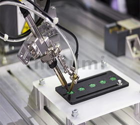 | 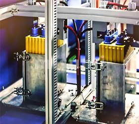 |
Part Number
CAD Data download and 3D preview are not available because the part number has not yet been determined.
- *In order to open the CAD Data download and 3D preview screen, the part number must be fixed.
- Please confirm the part number from "Specification / Dimension"on the left side, and then perform the CAD Data Download / 3D Preview operation.
| Part Number | Minimum order quantity | Volume Discount | Days to Ship | Table Size (Width) W (mm) | Table Size (Thickness) H (mm) | Position Change of Micrometer Knob |
|---|---|---|---|---|---|---|
| 1 Piece(s) | 10 Day(s) | 25 | 20 | Standard | ||
| 1 Piece(s) | 10 Day(s) | 25 | 20 | NR (Side Left and Right Reverse Type) | ||
| 1 Piece(s) | 10 Day(s) | 30 | 30 | Standard | ||
| 1 Piece(s) | 10 Day(s) | 30 | 30 | NR (Side Left and Right Reverse Type) | ||
| 1 Piece(s) | 10 Day(s) | 40 | 25 | Standard | ||
| 1 Piece(s) | 10 Day(s) | 40 | 25 | NR (Side Left and Right Reverse Type) | ||
| 1 Piece(s) | 10 Day(s) | 40 | 40 | Standard | ||
| 1 Piece(s) | 10 Day(s) | 40 | 40 | NR (Side Left and Right Reverse Type) | ||
| 1 Piece(s) | 10 Day(s) | 50 | 50 | Standard | ||
| 1 Piece(s) | 10 Day(s) | 50 | 50 | NR (Side Left and Right Reverse Type) | ||
| 1 Piece(s) | 10 Day(s) | 50 | 68 | Standard | ||
| 1 Piece(s) | 10 Day(s) | 50 | 68 | NR (Side Left and Right Reverse Type) | ||
| 1 Piece(s) | 10 Day(s) | 60 | 35 | Standard | ||
| 1 Piece(s) | 10 Day(s) | 60 | 35 | NR (Side Left and Right Reverse Type) | ||
| 1 Piece(s) | 10 Day(s) | 60 | 60 | Standard | ||
| 1 Piece(s) | 10 Day(s) | 60 | 60 | NR (Side Left and Right Reverse Type) | ||
| 1 Piece(s) | 10 Day(s) | 80 | 100 | Standard | ||
| 1 Piece(s) | 10 Day(s) | 80 | 100 | NR (Side Left and Right Reverse Type) |
Loading...
Specification/Dimensions
-
Table Size (Width) W(mm)
-
Table Size (Thickness) H(mm)
-
Position Change of Micrometer Knob
- NR (Side Left and Right Reverse Type)
- Standard
-
CAD
- 2D
- 3D
Days to Ship
-
- All
- 10 Day(s) or Less
Specify Alterations
- The specifications and dimensions of some parts may not be fully covered. For exact details, refer to manufacturer catalogs .
Frequently asked question (FAQ)
- Question: When a rotary stage is finely adjusted using a micrometer knob, how many degrees will the stage surface rotate as the micrometer knob moves 1mm?
- Answer: The micrometer knob moves 6.5mm as the stage surface rotates 10°. In other words, the stage surface rotates 1.538° as the micrometer knob moves 1mm.
- Question: What is the difference between lateral misalignment and surface runout of a rotary stage?
- Answer: Lateral misalignment refers to the displacement of a rotating central shaft in horizontal direction. Surface runout refers to the max. displacement difference relative to the reference plane after rotating one full turn, taking the outer edge of the stage moving surface fixed on the reference surface as the point of measurement. Both are in the unit of μm.
- Question: When using a manual rotary stage, is it normal that the clamping device on the opposite side of the micrometer knob still moves even locked after positioning?
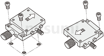
- Answer: MISUMI manual rotary stages can be finely adjusted after rough positioning. First of all, please lock the rough adjusting & clamping part according to the following steps: ①Adjust the feeding part to the destination (360° adjustable) ②Lock and fix the rough adjusting & clamping part ③Adjust the micrometer to the destination ④Lock the fine adjusting & clamping part.
- Question: Does a reverse manual rotary stage also have a reverse direction (counterclockwise) of reading (0~360°)?
- Answer: The direction of reading (0~360°) is clockwise for both R (forward) and L (reverse)?
Tech Support
-
Credit Card
Kartu Kredit
-
Bank TransferTransfer Bank
MISUMI Contact
MISUMI Kontak
Copyright © MISUMI Corporation All Rights Reserved.
How can we improve?Bagaimana Kami bisa meningkatkan Pelayanan?
How can we improve?Bagaimana Kami bisa meningkatkan Pelayanan?
While we are not able to respond directly to comments submitted in this form, the information will be reviewed for future improvement.
Customer Privacy Policy Walaupun Kami tidak dapat langsung menjawab saran yang ditulis di lembar ini, informasinya akan kami review untuk peningkatan pelayanan dikemudian hari
Kebijakan Privacy
Thank you for your cooperation.Terima kasih atas kerjasama anda.
While we are not able to respond directly to comments submitted in this form, the information will be reviewed for future improvement.
Please use the inquiry form.
Customer Privacy Policy Walaupun Kami tidak dapat langsung menjawab saran yang ditulis di lembar ini, informasinya akan kami review untuk peningkatan pelayanan dikemudian hari
Silahkan pergunakan Forms Permintaan.
Kebijakan Privacy