(!)Due to Microsoft's end of support for Internet Explorer 11 on 15/06/2022, this site does not support the recommended environment.
63,000 Stock items for Same Day Shipping
63,000 Item Stok untuk Pengiriman di Hari yang Sama
Search by Category / Brand
Pencarian dengan
Kategori / Merek
Search by Category Pencarian dengan Kategori
- Automation Components
A wide variety of standard and configurable components for factory automation engineers in industries such as automotive, semiconductor, packaging, medical and many more.
- Linear Motion
- Rotary Motion
- Connecting Parts
- Rotary Power Transmission
- Motors
- Conveyors & Material Handling
- Locating, Positioning, Jigs & Fixtures
- Inspection
- Sensors, Switches
- Pneumatics, Hydraulics
- Vacuum Components
- Hydraulic Equipment
- Discharging / Painting Devices
- Pipe, Tubes, Hoses & Fittings
- Modules, Units
- Heaters, Temperature Control
- Framing & Support
- Casters, Leveling Mounts, Posts
- Doors, Cabinet Hardware
- Springs, Shock Absorbers
- Adjusting, Fastening, Magnets
- Antivibration, Soundproofing Materials, Safety Products
- Fasteners
A good selection of accessories such as screws, bolts, washers and nuts that you may need for your daily engineering usage.
- Materials
Browse industrial materials ranging from heat insulating plates, sponges, to metal and plastic materials in different sizes to meet your various applications.
- Wiring Components
A wide variety of wiring parts for connecting and protecting control and PC parts including Connectors, Cables, Electric Wires, Crimping Terminals and more.
- LAN Cables / Industrial Network Cables
- Cables by Application
- Cables with Connectors
- RS232 / Personal Computers / AV Cables
- Wires/Cables
- Connectors (General Purpose)
- Crimp Terminals
- Zip Ties
- Cable Glands
- Cable Bushings/Clips/Stickers
- Screws/Spacers
- Cable Accessories
- Tubes
- Protection Tubes
- Ducts/Wiremolds
- General Purpose Tools
- Dedicated Tools
- Soldering Supplies
- Electrical & Controls
A wide variety of controls and PC parts for electrical engineers including Controls, Powers, PC parts and more.
- Cutting Tools
A wide variety of cutting tools for many uses and work materials including End Mills, Drills, Cutters, Reamers, Turning Tools and more.
- Carbide End Mills
- HSS End Mills
- Milling Cutter Inserts/Holders
- Customized Straight Blade End Mills
- Dedicated Cutters
- Turning Tools
- Drill Bits
- Screw-Hole-Related Tools
- Reamers
- Chamfering / Centering Tools
- Fixtures Related to Cutting Tools
- Step Drills
- Hole Saws
- Clean Key Cutters
- Core Drills (Tip Tools)
- Magnetic Drilling Machine Cutters
- Drill Bits for Electric Drilling Machines
- Woodworking Drill Cutters
- Drills for Concrete
- Processing Tools
A wide variety of tools and supplies used in processing including Machine Tools, Measurement Tools, Grinding and Polishing Supplies and more.
- Material Handling & Storage
A wide variety of goods used in shipment, material handling and warehouse including Tape supplies, Stretch film, Truck, Shelf, Crane and more.
- Tape Supplies
- Cushioning Materials
- Stretch Films
- Cardboard
- Plastic Bags
- PP Bands
- Magic Tapes / Tying Belts
- Rubber Bands
- Strings/Ropes
- Cable Ties
- Tags
- Labelers
- Unpacking Cutters
- Packing Support Equipment
- Cloth Sheets for Packing
- Conveyance/Dolly Carts
- Tool Wagons
- Tool Cabinets / Container Racks
- Lifters / Hand Pallets
- Container Pallets
- Storage Supplies
- Shelves/Racks
- Work Benches
- Suspended Clamps/Suspended Belts
- Jack Winches
- Chain Block Cranes
- Bottles/Containers
- Bicycle Storage Area
- Safety & General Supplies
A large variety of goods for every kind of factories and offices including Protection items, Cleaning supplies, sanitations, office supplies and more.
- Lab & Clean Room Supplies
A large variety of items used in R&D and Clean Room including research Equipment, Laboratory Essentials, Analysis Supplies, Clean Environment-Related Equipment and more.
- Press Die Components
Choose from thousands of standard stamping die components including Punch & Die, Gas Springs, Guide Components, Coil Springs and many more.
- Plastic Mold Components
Browse our wide variety of mold components including Ejector Pins, Sleeves, Leader Components, Sprue Bushings and many more.
- Ejector Pins
- Sleeves, Center Pins
- Core Pins
- Sprue bushings, Gates, and other components
- Date Mark Inserts, Recycle Mark Inserts, Pins with Gas Vent
- Undercut, Plates
- Leader Components, Components for Ejector Space
- Mold Opening Controllers
- Cooling or Heating Components
- Accessories, Others
- Components of Large Mold, Die Casting
- Injection Molding Components
Browse our injection molding components including Heating Items, Couplers, Hoses and more.
- Injection Molding Machine Products
- Accessories of Equipment
- Auxiliary Equipment
- Air Nippers
- Air Cylinders
- Air Chuck for Runner
- Chuck Board Components
- Frames
- Suction Components
- Parallel Air Chuck
- Special Air Chuck
- Chemical for Injection Molding
- Mold Maintenance
- Heating Items
- Heat Insulation Sheets
- Couplers, Plugs, One-touch Joints
- Tubes, Hoses, Peripheral Components
- Komponen Mekanis
- Linear Motion
- Rotary Motion
- Connecting Parts
- Rotary Power Transmission
- Motors
- Conveyors & Material Handling
- Locating, Positioning, Jigs & Fixtures
- Inspection
- Sensors, Switches
- Pneumatics, Hydraulics
- Vacuum Components
- Hydraulic Equipment
- Discharging / Painting Devices
- Pipe, Tubes, Hoses & Fittings
- Modules, Units
- Heaters, Temperature Control
- Framing & Support
- Casters, Leveling Mounts, Posts
- Doors, Cabinet Hardware
- Springs, Shock Absorbers
- Adjusting, Fastening, Magnets
- Antivibration, Soundproofing Materials, Safety Products
- Sekrup, Baut, Washer, Nut
- Material
- Komponen Kabel
- LAN Cables / Industrial Network Cables
- Cables by Application
- Cables with Connectors
- RS232 / Personal Computers / AV Cables
- Wires/Cables
- Connectors (General Purpose)
- Crimp Terminals
- Zip Ties
- Cable Glands
- Cable Bushings/Clips/Stickers
- Screws/Spacers
- Cable Accessories
- Tubes
- Protection Tubes
- Ducts/Wiremolds
- General Purpose Tools
- Dedicated Tools
- Soldering Supplies
- Elektrikal & Kontrol
- Peralatan Pemotong
- Carbide End Mills
- HSS End Mills
- Milling Cutter Inserts/Holders
- Customized Straight Blade End Mills
- Dedicated Cutters
- Turning Tools
- Drill Bits
- Screw-Hole-Related Tools
- Reamers
- Chamfering / Centering Tools
- Fixtures Related to Cutting Tools
- Step Drills
- Hole Saws
- Clean Key Cutters
- Core Drills (Tip Tools)
- Magnetic Drilling Machine Cutters
- Drill Bits for Electric Drilling Machines
- Woodworking Drill Cutters
- Drills for Concrete
- Peralatan Produksi
- Penanganan Material & Penyimpanan
- Tape Supplies
- Cushioning Materials
- Stretch Films
- Cardboard
- Plastic Bags
- PP Bands
- Magic Tapes / Tying Belts
- Rubber Bands
- Strings/Ropes
- Cable Ties
- Tags
- Labelers
- Unpacking Cutters
- Packing Support Equipment
- Cloth Sheets for Packing
- Conveyance/Dolly Carts
- Tool Wagons
- Tool Cabinets / Container Racks
- Lifters / Hand Pallets
- Container Pallets
- Storage Supplies
- Shelves/Racks
- Work Benches
- Suspended Clamps/Suspended Belts
- Jack Winches
- Chain Block Cranes
- Bottles/Containers
- Bicycle Storage Area
- Perlengkapan Keamanan & Umum
- Perlengkapan Sanitasi & Lab
- Komponen Press Die
- Komponen Plastik Mold
- Ejector Pins
- Sleeves, Center Pins
- Core Pins
- Sprue bushings, Gates, and other components
- Date Mark Inserts, Recycle Mark Inserts, Pins with Gas Vent
- Undercut, Plates
- Leader Components, Components for Ejector Space
- Mold Opening Controllers
- Cooling or Heating Components
- Accessories, Others
- Components of Large Mold, Die Casting
- Komponen Injeksi Moulding
- Injection Molding Machine Products
- Accessories of Equipment
- Auxiliary Equipment
- Air Nippers
- Air Cylinders
- Air Chuck for Runner
- Chuck Board Components
- Frames
- Suction Components
- Parallel Air Chuck
- Special Air Chuck
- Chemical for Injection Molding
- Mold Maintenance
- Heating Items
- Heat Insulation Sheets
- Couplers, Plugs, One-touch Joints
- Tubes, Hoses, Peripheral Components
Search by Brand Pencarian dengan Merek


This translation is a Google translation Terjemahan ini adalah terjemahan Google
- Pembayaran dengan kartu kredit untuk sementara tidak tersedia karena kendala sistem.
Sementara waktu Anda dapat meggunakan metode Pembayaran di Muka atau QRIS.
Untuk informasi lebih lanjut, silakan hubungi Customer Service :
TEL: 021-8984-0008 E-mail: cs@misumi.co.id. WA: 08118984008.
Kami mohon maaf atas ketidaknyamanan yang terjadi.
Credit card payments are temporarily unavailable due to system issues. Meanwhile, you can use the Advance Payment method or QRIS. For further information, please contact Customer Service: TEL: 021-8984-0008 E-mail: cs@misumi.co.id. WA: 08118984008. We apologize for any inconvenience caused.
- Sehubungan dengan adanya Peraturan Baru Kementerian Perdagangan No.36 Tahun 2023 tentang Pembatasan Impor Barang, MISUMI Indonesia melakukan tindakan pencegahan. Lihat informasi detailnya di sini
Due to New Regulation of Ministry Of Trade No.36 of 2023 concerning retrictions on imports of goods, MISUMI Indonesia do precautions measure. See detail information here - Nomor telepon alternatif Kontak Layanan Pelanggan : 021-29182911| 021-29182991 | 021-29182997 | 021-29182998
Alternative telephone number Contact Customer Service: 021-29182911 | 021-29182991 | 021-29182997 | 021-29182998
MIL connector IDC female connector (no lock)
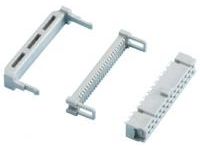
[Features]This is a female connector that allows for batch IDC together with 1.27 mm pitch ribbon cable. It is a lead-free type that takes into consideration the global environment. A standard MIL connector that is compliant with the MIL standard (MIL-C-83503) and UL-certified.
- UL
- MIL
- For Signal
- Connection between Boards
- Solenoid Valve
- PLC
- Pressure Welding
- Gold Plated

● Lead-free solder for environmental considerations.
● A standard MIL connector compliant with MIL specifications (MIL-C-83503) and with UL acquisition.
● UL No. E68080
● UL No. E45587 (Strain Relief)

| Rated Current | Rated Voltage | Connection Resistance | Insulation Resistance | Withstand Voltage | Operating Temperature |
| 1A | AC250V | Below 20 mΩ | 1000 MΩ or more | 1,000 VAC r.m.s / 1 min. | -55°C – 105°C |

· Compatible Wire Size: AWG28 or 0.08 mm2 Stranded 1.27 mm Pitch Flat Cables, Fusion Cable
Japanese Only
Part Number
Configured Part Number is shown.
7940-B500FL-3448
Specifications

| Model | Number of Cores | Weight g |
| 7910-B500FL-3448 | 10 | 2.00 |
| 7914-B500FL-3448 | 14 | 2.59 |
| 7916-B500FL-3448 | 16 | 2.88 |
| 7920-B500FL-3448 | 20 | 3.48 |
| 7926-B500FL-3448 | 26 | 4.36 |
| 7930-B500FL-3448 | 30 | 4.96 |
| 7934-B500FL-3448 | 34 | 5.54 |
| 7940-B500FL-3448 | 40 | 6.43 |
| 7950-B500FL-3448 | 50 | 7.89 |
| 7950-B700FL-3448 | 50 | 7.91 |
| 7960-B500FL-3448 | 60 | 9.39 |
| 7964-B500FL-3448 | 64 | 9.99 |
More Information
[ M ]Material / Finish
| Item | Materials | Finish |
| Contact | Copper Alloy | Nickel Plating Gold Base Plating |
| Body | Glass Reinforced Polyester | UL94V-0, Gray |
| Cover | Glass-filled Polyester | |
| Strain Relief | Polyester |
| Part Number |
|---|
| 7940-B500FL-3448 |
| Part Number | Minimum order quantity | Volume Discount | Days to Ship |
|---|---|---|---|
| 1 Piece(s) | 16 Day(s) or more |
Loading...
Connection Method for Pressure Welding Type MIL Socket Connector


Table of Possible Connectors for Pressure Welding
| Product Name | Model |
|---|---|
| D-sub Connector (EMI Pressure Welding Type) |
FD*-*PF05 (Male) FD*-*P05 (Male) FD*-*S05 (Female) |
| Centronics Connector General-purpose Pressure Welding Spring-lock Type |
57F-30***-20S (Male) 57F-40***-20S (Female) |
| Centronics Connector (EMI Pressure Welding Type) |
57FE-30***-20N-D8 (Male) 57FE-40***-20N-D8 (Female) |
| FCN Pressure Welded Connector | FCN-367J***-AU-F (Female) |
| MIL Socket Connector Female Pressure Welding Contact Connector (without Lock) |
HIF3**-**D-2.54R (Female) 79**-B500FL-3448 * Cannot be used for 60 / 64 core type. The type with 2 guide keys also cannot be used |
| MIL Socket Connector Female Pressure Welding Contact Connector (with Lock) |
XG4M-****-U |
Basic Information
| Connector Shape | Square shape | Connector series initials | M/N/O | M/N/O | MIL |
|---|---|---|---|---|---|
| Applicable pin/contact | Female (socket) | Number of Pins | 40 | Application | Cable to Circuit Board |
| Allowable Current(A) | 1 | Allowable Voltage(V) | 250 | Wire connection method | Pressure welding |
| Connection direction | Straight | Protection function (environmentally resistant) | None | Representative Standard | UL |
| Polarity Guide/Slot(Piece) | Central 1 | Polarizing key groove/key mount(Piece) | Left and Right Each 1 | Other standards (MIL) | ○ |
| Removal method | Others |
Please check the type/dimensions/specifications of the part 7940-B500FL-3448 in the MIL connector IDC female connector (no lock) series.
- The specifications and dimensions of some parts may not be fully covered. For exact details, refer to manufacturer catalogs .
Tech Support
- Wiring parts/Control and PC Parts
- Tel:021-8990-4102 / FAX:021-8990-5803
- 8:30am - 5:30pm (Monday - Friday)
- Technical Inquiry
-
Credit Card
Kartu Kredit
-
Bank TransferTransfer Bank
MISUMI Contact
MISUMI Kontak
Copyright © MISUMI Corporation All Rights Reserved.
How can we improve?Bagaimana Kami bisa meningkatkan Pelayanan?
How can we improve?Bagaimana Kami bisa meningkatkan Pelayanan?
While we are not able to respond directly to comments submitted in this form, the information will be reviewed for future improvement.
Customer Privacy Policy Walaupun Kami tidak dapat langsung menjawab saran yang ditulis di lembar ini, informasinya akan kami review untuk peningkatan pelayanan dikemudian hari
Kebijakan Privacy
Thank you for your cooperation.Terima kasih atas kerjasama anda.
While we are not able to respond directly to comments submitted in this form, the information will be reviewed for future improvement.
Please use the inquiry form.
Customer Privacy Policy Walaupun Kami tidak dapat langsung menjawab saran yang ditulis di lembar ini, informasinya akan kami review untuk peningkatan pelayanan dikemudian hari
Silahkan pergunakan Forms Permintaan.
Kebijakan Privacy