(!)Due to Microsoft's end of support for Internet Explorer 11 on 15/06/2022, this site does not support the recommended environment.
63,000 Stock items for Same Day Shipping
63,000 Item Stok untuk Pengiriman di Hari yang Sama
Search by Category / Brand
Pencarian dengan
Kategori / Merek
Search by Category Pencarian dengan Kategori
- Automation Components
A wide variety of standard and configurable components for factory automation engineers in industries such as automotive, semiconductor, packaging, medical and many more.
- Linear Motion
- Rotary Motion
- Connecting Parts
- Rotary Power Transmission
- Motors
- Conveyors & Material Handling
- Locating, Positioning, Jigs & Fixtures
- Inspection
- Sensors, Switches
- Pneumatics, Hydraulics
- Vacuum Components
- Hydraulic Equipment
- Discharging / Painting Devices
- Pipe, Tubes, Hoses & Fittings
- Modules, Units
- Heaters, Temperature Control
- Framing & Support
- Casters, Leveling Mounts, Posts
- Doors, Cabinet Hardware
- Springs, Shock Absorbers
- Adjusting, Fastening, Magnets
- Antivibration, Soundproofing Materials, Safety Products
- Fasteners
A good selection of accessories such as screws, bolts, washers and nuts that you may need for your daily engineering usage.
- Materials
Browse industrial materials ranging from heat insulating plates, sponges, to metal and plastic materials in different sizes to meet your various applications.
- Wiring Components
A wide variety of wiring parts for connecting and protecting control and PC parts including Connectors, Cables, Electric Wires, Crimping Terminals and more.
- LAN Cables / Industrial Network Cables
- Cables by Application
- Cables with Connectors
- RS232 / Personal Computers / AV Cables
- Wires/Cables
- Connectors (General Purpose)
- Crimp Terminals
- Zip Ties
- Cable Glands
- Cable Bushings/Clips/Stickers
- Screws/Spacers
- Cable Accessories
- Tubes
- Protection Tubes
- Ducts/Wiremolds
- General Purpose Tools
- Dedicated Tools
- Soldering Supplies
- Electrical & Controls
A wide variety of controls and PC parts for electrical engineers including Controls, Powers, PC parts and more.
- Cutting Tools
A wide variety of cutting tools for many uses and work materials including End Mills, Drills, Cutters, Reamers, Turning Tools and more.
- Carbide End Mills
- HSS End Mills
- Milling Cutter Inserts/Holders
- Customized Straight Blade End Mills
- Dedicated Cutters
- Turning Tools
- Drill Bits
- Screw-Hole-Related Tools
- Reamers
- Chamfering / Centering Tools
- Fixtures Related to Cutting Tools
- Step Drills
- Hole Saws
- Clean Key Cutters
- Core Drills (Tip Tools)
- Magnetic Drilling Machine Cutters
- Drill Bits for Electric Drilling Machines
- Woodworking Drill Cutters
- Drills for Concrete
- Processing Tools
A wide variety of tools and supplies used in processing including Machine Tools, Measurement Tools, Grinding and Polishing Supplies and more.
- Material Handling & Storage
A wide variety of goods used in shipment, material handling and warehouse including Tape supplies, Stretch film, Truck, Shelf, Crane and more.
- Tape Supplies
- Cushioning Materials
- Stretch Films
- Cardboard
- Plastic Bags
- PP Bands
- Magic Tapes / Tying Belts
- Rubber Bands
- Strings/Ropes
- Cable Ties
- Tags
- Labelers
- Unpacking Cutters
- Packing Support Equipment
- Cloth Sheets for Packing
- Conveyance/Dolly Carts
- Tool Wagons
- Tool Cabinets / Container Racks
- Lifters / Hand Pallets
- Container Pallets
- Storage Supplies
- Shelves/Racks
- Work Benches
- Suspended Clamps/Suspended Belts
- Jack Winches
- Chain Block Cranes
- Bottles/Containers
- Bicycle Storage Area
- Safety & General Supplies
A large variety of goods for every kind of factories and offices including Protection items, Cleaning supplies, sanitations, office supplies and more.
- Lab & Clean Room Supplies
A large variety of items used in R&D and Clean Room including research Equipment, Laboratory Essentials, Analysis Supplies, Clean Environment-Related Equipment and more.
- Press Die Components
Choose from thousands of standard stamping die components including Punch & Die, Gas Springs, Guide Components, Coil Springs and many more.
- Plastic Mold Components
Browse our wide variety of mold components including Ejector Pins, Sleeves, Leader Components, Sprue Bushings and many more.
- Ejector Pins
- Sleeves, Center Pins
- Core Pins
- Sprue bushings, Gates, and other components
- Date Mark Inserts, Recycle Mark Inserts, Pins with Gas Vent
- Undercut, Plates
- Leader Components, Components for Ejector Space
- Mold Opening Controllers
- Cooling or Heating Components
- Accessories, Others
- Components of Large Mold, Die Casting
- Injection Molding Components
Browse our injection molding components including Heating Items, Couplers, Hoses and more.
- Injection Molding Machine Products
- Accessories of Equipment
- Auxiliary Equipment
- Air Nippers
- Air Cylinders
- Air Chuck for Runner
- Chuck Board Components
- Frames
- Suction Components
- Parallel Air Chuck
- Special Air Chuck
- Chemical for Injection Molding
- Mold Maintenance
- Heating Items
- Heat Insulation Sheets
- Couplers, Plugs, One-touch Joints
- Tubes, Hoses, Peripheral Components
- Komponen Mekanis
- Linear Motion
- Rotary Motion
- Connecting Parts
- Rotary Power Transmission
- Motors
- Conveyors & Material Handling
- Locating, Positioning, Jigs & Fixtures
- Inspection
- Sensors, Switches
- Pneumatics, Hydraulics
- Vacuum Components
- Hydraulic Equipment
- Discharging / Painting Devices
- Pipe, Tubes, Hoses & Fittings
- Modules, Units
- Heaters, Temperature Control
- Framing & Support
- Casters, Leveling Mounts, Posts
- Doors, Cabinet Hardware
- Springs, Shock Absorbers
- Adjusting, Fastening, Magnets
- Antivibration, Soundproofing Materials, Safety Products
- Sekrup, Baut, Washer, Nut
- Material
- Komponen Kabel
- LAN Cables / Industrial Network Cables
- Cables by Application
- Cables with Connectors
- RS232 / Personal Computers / AV Cables
- Wires/Cables
- Connectors (General Purpose)
- Crimp Terminals
- Zip Ties
- Cable Glands
- Cable Bushings/Clips/Stickers
- Screws/Spacers
- Cable Accessories
- Tubes
- Protection Tubes
- Ducts/Wiremolds
- General Purpose Tools
- Dedicated Tools
- Soldering Supplies
- Elektrikal & Kontrol
- Peralatan Pemotong
- Carbide End Mills
- HSS End Mills
- Milling Cutter Inserts/Holders
- Customized Straight Blade End Mills
- Dedicated Cutters
- Turning Tools
- Drill Bits
- Screw-Hole-Related Tools
- Reamers
- Chamfering / Centering Tools
- Fixtures Related to Cutting Tools
- Step Drills
- Hole Saws
- Clean Key Cutters
- Core Drills (Tip Tools)
- Magnetic Drilling Machine Cutters
- Drill Bits for Electric Drilling Machines
- Woodworking Drill Cutters
- Drills for Concrete
- Peralatan Produksi
- Penanganan Material & Penyimpanan
- Tape Supplies
- Cushioning Materials
- Stretch Films
- Cardboard
- Plastic Bags
- PP Bands
- Magic Tapes / Tying Belts
- Rubber Bands
- Strings/Ropes
- Cable Ties
- Tags
- Labelers
- Unpacking Cutters
- Packing Support Equipment
- Cloth Sheets for Packing
- Conveyance/Dolly Carts
- Tool Wagons
- Tool Cabinets / Container Racks
- Lifters / Hand Pallets
- Container Pallets
- Storage Supplies
- Shelves/Racks
- Work Benches
- Suspended Clamps/Suspended Belts
- Jack Winches
- Chain Block Cranes
- Bottles/Containers
- Bicycle Storage Area
- Perlengkapan Keamanan & Umum
- Perlengkapan Sanitasi & Lab
- Komponen Press Die
- Komponen Plastik Mold
- Ejector Pins
- Sleeves, Center Pins
- Core Pins
- Sprue bushings, Gates, and other components
- Date Mark Inserts, Recycle Mark Inserts, Pins with Gas Vent
- Undercut, Plates
- Leader Components, Components for Ejector Space
- Mold Opening Controllers
- Cooling or Heating Components
- Accessories, Others
- Components of Large Mold, Die Casting
- Komponen Injeksi Moulding
- Injection Molding Machine Products
- Accessories of Equipment
- Auxiliary Equipment
- Air Nippers
- Air Cylinders
- Air Chuck for Runner
- Chuck Board Components
- Frames
- Suction Components
- Parallel Air Chuck
- Special Air Chuck
- Chemical for Injection Molding
- Mold Maintenance
- Heating Items
- Heat Insulation Sheets
- Couplers, Plugs, One-touch Joints
- Tubes, Hoses, Peripheral Components
Search by Brand Pencarian dengan Merek


This translation is a Google translation Terjemahan ini adalah terjemahan Google
- Sehubungan dengan adanya Peraturan Baru Kementerian Perdagangan No.36 Tahun 2023 tentang Pembatasan Impor Barang, MISUMI Indonesia melakukan tindakan pencegahan. Lihat informasi detailnya di sini
Due to New Regulation of Ministry Of Trade No.36 of 2023 concerning retrictions on imports of goods, MISUMI Indonesia do precautions measure. See detail information here - Nomor telepon alternatif Kontak Layanan Pelanggan : 021-29182911| 021-29182991 | 021-29182997 | 021-29182998
Alternative telephone number Contact Customer Service: 021-29182911 | 021-29182991 | 021-29182997 | 021-29182998
Drive Device, Guided Twin Rod Cylinder B Series, Double Acting Type
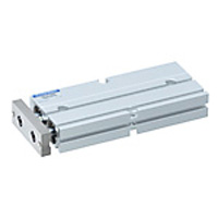
Flat, square shaped, compact design without guide, space efficient and low cost.
(i)Caution
- [Information About the End of Sales]Part number: TBDA20 × 100-NCU will be discontinued in April 2022.
Japanese Only
Part Number
Configured Part Number is shown.
Drawing
⌀10

Rod end
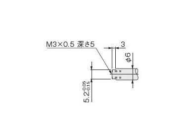
⌀16 to ⌀20

Rod end

Product Specifications
| Items | Cylinder diameter mm | ||
|---|---|---|---|
| 10 | 16 | 20 | |
| Operation type | Double acting type | ||
| Operating fluid | Air | ||
| Mounting Type | Side Mount | ||
| Operating pressure range MPa | 0.15 to 0.7 | 0.1 to 0.7 | |
| Guaranteed pressure resistant MPa | 1.05 | ||
| Operating temperature range °C | 0 to 60 | ||
| Operating speed range mm/s | 100 to 500 | ||
| Cushion | Rubber bumper method | ||
| Lubrication | Not required (When refueling, turbine oil type 1 "ISO VG32" equivalent) | ||
| Non-rotating accuracy | ±0.4° | ±0.3° | |
| Stroke adjustment range mm | -5 to 0 (To the specification stroke) | ||
| Piping connection port diameter | M5 × 0.8 | ||
Cylinder diameter and stroke
| Diameter | Standard stroke | Can be manufactured Maximum stroke | Pull side stroke Adjustment range |
|---|---|---|---|
| 10 | 10, 20, 30, 40, 50, 60, 70 | 140 | -5 to 0 |
| 16 | 10, 20, 30, 40, 50, 60, 70 80, 90, 100 | 200 | |
| 20 | 10, 20, 30, 40, 50, 60, 70 80, 90, 100 | 200 |
Internal structure and name of each part
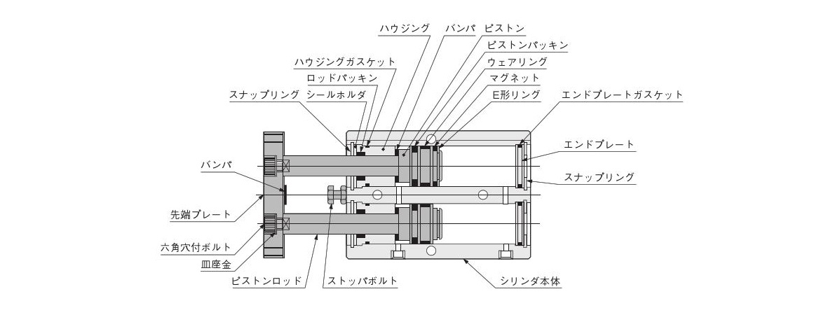
Material of main parts
| Name | Materials |
|---|---|
| Standard specifications | |
| Cylinder main body | Aluminum alloy (Anodizing) |
| Piston | Aluminum alloy (Special rust prevention treatment) |
| Wear ring | Resin (Non-fluoropolymer resin^*) |
| Piston rod | Hard steel (Chrome plating) |
| Gasket | Synthetic rubber (NBR) |
| Seal holder | Mild steel (Nickel plating) |
| Housing | Aluminum alloy (Special abrasion resistance treatment) |
| End plate | Resin (ø32 only aluminum alloy (anodizing)) |
| Packing | Synthetic rubber (NBR) |
| Retaining Ring | Hard steel (Nickel plating) |
| Magnet | Resin magnet |
| Retaining ring | Stainless steel |
| Plate washer | Hard steel (Nickel plating) |
| End plate | Mild steel (Nickel plating) |
| Bumper | Synthetic rubber (NBR) |
| Stopper bolt | Mild steel (Zinc plating) |
*: For ø25/32 (diameter 25/32 mm) non-ion specifications.
Notes: ø10/16/20 (diameter 10/16/20 mm) can use standard specifications as non-ion specifications
Standard table
| Symbol | A | B | C | D | E | F | G | H | I | J | K | L | M | ||||||||||
|---|---|---|---|---|---|---|---|---|---|---|---|---|---|---|---|---|---|---|---|---|---|---|---|
| Stroke | 10 | 20 | 30 | 40 | 50 | 60 | 70 | 80 | 90 | 100 | |||||||||||||
| Diameter | 16 | 68 | 15 | 53 | 20 | 30 | 35 | 40 | 45 | 50 | 55 | 60 | 65 | 70 | 75 | 8 | 47 | 6 | 24 | M4 × 0.7, Depth 5 | 47 | 53 | 20 |
| 20 | 78 | 20 | 58 | 20 | 35 | 35 | 40 | 45 | 50 | 55 | 60 | 65 | 70 | 75 | 10 | 55 | 9 | 28 | M4 × 0.7, Depth 5 | 55 | 61 | 24 | |
| Symbol | N1 | N2 | P^1^* | Q | R | S | T | V | W | Y | Z | |
|---|---|---|---|---|---|---|---|---|---|---|---|---|
| Diameter | 16 | 22 | 10 | ⌀4.5 (through hole) Counterbore ø8 Depth 5.5 (both sides) | 34 | 4 | 54 | 21 | 8 | 6.2 | 18.5 | 5.7 |
| 20 | 25 | 12 | ⌀4.5 (through hole) Counterbore ø8 Depth 5.5 (both sides) | 44 | 6 | 62 | 25 | 10 | 8.2 | 20 | 6.8 | |
*: The counterbore depth is the value from the top of the main body.
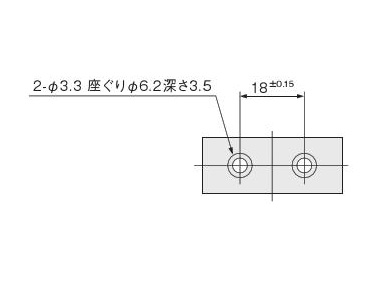
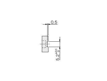
| Symbol | PA | PB | PC | PD | PE | PF | PG | PH | |
|---|---|---|---|---|---|---|---|---|---|
| Diameter | 16 | 24 | 1 | ø4.3 Counterbore ø7.8 Depth 4.6 | 6.2 (+0.1 to 0) | 8 | 3 | 6.2 (-0.05 to -0.15) | M4 × 0.7, Depth 6 |
| 20 | 28 | 1 | ø6.5 Counterbore ø11 Depth 6.8 | 8.2 (+0.1 to 0) | 10 | 3 | 8.2 (-0.05 to -0.15) | M6 × 1, Depth 8 | |
Product features details
Allowable lateral load
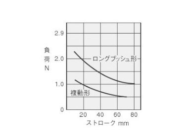
ø10 (diameter 10 mm) lateral load graph
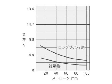
ø16 (diameter 16 mm) lateral load graph
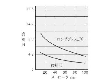
ø20 (diameter 20 mm) lateral load graph
Behind the scenes
This product was developed through rigorous testing to meet the customers' needs by combining the design expertise and production technology that the manufacturer has cultivated since its founding.
| Part Number | Minimum order quantity | Volume Discount | Days to Ship | Cylinder I.D: D (Ø) | Stroke: L (mm) | Environment, Applications | End Locking | Valves | Operating Pressure (MPa) | Sensor specifications | Guide Structure | Sensor Switches | Lead Wire Length | Number of sensor switches | Max. Operating Pressure (MPa) |
|---|---|---|---|---|---|---|---|---|---|---|---|---|---|---|---|
| 1 Piece(s) | 16 Day(s) or more | 10 | 10 | Non-use of Copper and fluoropolymer-based Material (Partially Plating) | No | No | - | No | Push Type | - | - | - | 0.7 | ||
| 1 Piece(s) | 16 Day(s) or more | 10 | 20 | Non-use of Copper and fluoropolymer-based Material (Partially Plating) | No | No | - | No | Push Type | - | - | - | 0.7 | ||
| 1 Piece(s) | 16 Day(s) or more | 10 | 30 | Non-use of Copper and fluoropolymer-based Material (Partially Plating) | No | No | - | No | Push Type | - | - | - | 0.7 | ||
| 1 Piece(s) | 14 Day(s) or more | 10 | 30 | Standard | - | - | 0.15~0.7 | - | - | ZE275 | 3,000 mm | 2 | - | ||
| 1 Piece(s) | 16 Day(s) or more | 10 | 50 | Non-use of Copper and fluoropolymer-based Material (Partially Plating) | No | No | - | No | Push Type | - | - | - | 0.7 | ||
| 1 Piece(s) | 14 Day(s) or more | 10 | 50 | Standard | - | - | 0.15~0.7 | - | - | ZE101 | 1,000 mm | 2 | - | ||
| 1 Piece(s) | 14 Day(s) or more | 10 | 60 | Standard | - | - | 0.15~0.7 | - | - | ZE101 | 1,000 mm | 2 | - | ||
| 1 Piece(s) | 16 Day(s) or more | 16 | 20 | Non-use of Copper and fluoropolymer-based Material (Partially Plating) | No | No | - | No | Push Type | - | - | - | 0.7 | ||
| 1 Piece(s) | 14 Day(s) or more | 16 | 20 | Standard | - | - | 0.1~0.7 | - | - | ZE175 | 1,000 mm | 2 | - | ||
| 1 Piece(s) | 14 Day(s) or more | 16 | 20 | Standard | - | - | 0.1~0.7 | - | - | ZE275 | 1,000 mm | 2 | - | ||
| 1 Piece(s) | 16 Day(s) or more | 16 | 30 | Non-use of Copper and fluoropolymer-based Material (Partially Plating) | No | No | - | No | Push Type | - | - | - | 0.7 | ||
| 1 Piece(s) | 16 Day(s) or more | 16 | 40 | Non-use of Copper and fluoropolymer-based Material (Partially Plating) | No | No | - | No | Push Type | - | - | - | 0.7 | ||
| 1 Piece(s) | 14 Day(s) or more | 16 | 40 | Standard | - | - | 0.1~0.7 | - | - | ZE101 | 1,000 mm | 2 | - | ||
| 1 Piece(s) | 16 Day(s) or more | 16 | 60 | Non-use of Copper and fluoropolymer-based Material (Partially Plating) | No | No | - | No | Push Type | - | - | - | 0.7 | ||
| 1 Piece(s) | 16 Day(s) or more | 16 | 70 | Non-use of Copper and fluoropolymer-based Material (Partially Plating) | No | No | - | No | Push Type | - | - | - | 0.7 | ||
| 1 Piece(s) | 14 Day(s) or more | 16 | 70 | Standard | - | - | 0.1~0.7 | - | - | ZE101 | 1,000 mm | 2 | - | ||
| 1 Piece(s) | 16 Day(s) or more | 16 | 80 | Non-use of Copper and fluoropolymer-based Material (Partially Plating) | No | No | - | No | Push Type | - | - | - | 0.7 | ||
| 1 Piece(s) | 14 Day(s) or more | 16 | 90 | Standard | - | - | 0.1~0.7 | - | - | ZE101 | 1,000 mm | 2 | - | ||
| 1 Piece(s) | 16 Day(s) or more | 16 | 100 | Non-use of Copper and fluoropolymer-based Material (Partially Plating) | No | No | - | No | Push Type | - | - | - | 0.7 | ||
| 1 Piece(s) | 14 Day(s) or more | 16 | 100 | Standard | - | - | 0.1~0.7 | - | - | ZE175 | 1,000 mm | 2 | - | ||
| 1 Piece(s) | 16 Day(s) or more | 20 | 20 | Non-use of Copper and fluoropolymer-based Material (Partially Plating) | No | No | - | No | Push Type | - | - | - | 0.7 | ||
| 1 Piece(s) | 16 Day(s) or more | 20 | 30 | Non-use of Copper and fluoropolymer-based Material (Partially Plating) | No | No | - | No | Push Type | - | - | - | 0.7 | ||
| 1 Piece(s) | 16 Day(s) or more | 20 | 40 | Non-use of Copper and fluoropolymer-based Material (Partially Plating) | No | No | - | No | Push Type | - | - | - | 0.7 | ||
| 1 Piece(s) | 14 Day(s) or more | 32 | 80 | Standard | - | - | 0.1~0.7 | - | - | ZE155 | 3,000 mm | 2 | - | ||
| 1 Piece(s) | 14 Day(s) or more | 32 | 100 | Standard | - | - | 0.1~0.7 | - | - | ZE101 | 1,000 mm | 2 | - | ||
| 1 Piece(s) | 14 Day(s) or more | 32 | 100 | Standard | - | - | 0.1~0.7 | - | - | ZE255 | 1,000 mm | 2 | - |
Loading...
Basic Information
| Cylinder Operation Method | Double Acting | Rod Operation Method | Single Rods | Main Body Shape | Guided |
|---|---|---|---|---|---|
| Additional Function | High rigidity / high precision high class guide / With rod detent function / Stroke with Adjustment | Operating Temperature(°C) | 0::60 |
Specification/Dimensions
-
Cylinder I.D: D(Ø)
-
Stroke: L(mm)
-
Environment, Applications
- Standard
- Non-use of Copper and fluoropolymer-based Material (Partially Plating)
-
End Locking
- No
-
Valves
- No
-
Sensor specifications
- No
-
Guide Structure
- Push Type
-
Sensor Switches
-
Lead Wire Length
- 1,000 mm
- 3,000 mm
-
Number of sensor switches
- 2
-
Max. Operating Pressure(MPa)
- 0.7
-
type
- TBDA
-
CAD
- 2D
- 3D
Days to Ship
-
- All
- 14 Day(s) or Less
- 16 Day(s) or Less
Specify Alterations
- The specifications and dimensions of some parts may not be fully covered. For exact details, refer to manufacturer catalogs .
Tech Support
- Factory Automation, Electronics, Tools, & MRO (Maintenance, Repair and Operations)
- Tel:021-8990-4102 / FAX:021-8990-5803
- 8:30am - 5:30pm (Monday - Friday)
- Technical Inquiry
-
Credit Card
Kartu Kredit
-
Bank TransferTransfer Bank
MISUMI Contact
MISUMI Kontak
Copyright © MISUMI Corporation All Rights Reserved.
How can we improve?Bagaimana Kami bisa meningkatkan Pelayanan?
How can we improve?Bagaimana Kami bisa meningkatkan Pelayanan?
While we are not able to respond directly to comments submitted in this form, the information will be reviewed for future improvement.
Customer Privacy Policy Walaupun Kami tidak dapat langsung menjawab saran yang ditulis di lembar ini, informasinya akan kami review untuk peningkatan pelayanan dikemudian hari
Kebijakan Privacy
Thank you for your cooperation.Terima kasih atas kerjasama anda.
While we are not able to respond directly to comments submitted in this form, the information will be reviewed for future improvement.
Please use the inquiry form.
Customer Privacy Policy Walaupun Kami tidak dapat langsung menjawab saran yang ditulis di lembar ini, informasinya akan kami review untuk peningkatan pelayanan dikemudian hari
Silahkan pergunakan Forms Permintaan.
Kebijakan Privacy