(!)Due to Microsoft's end of support for Internet Explorer 11 on 15/06/2022, this site does not support the recommended environment.
63,000 Stock items for Same Day Shipping
63,000 Item Stok untuk Pengiriman di Hari yang Sama
Search by Category / Brand
Pencarian dengan
Kategori / Merek
Search by Category Pencarian dengan Kategori
- Automation Components
A wide variety of standard and configurable components for factory automation engineers in industries such as automotive, semiconductor, packaging, medical and many more.
- Linear Motion
- Rotary Motion
- Connecting Parts
- Rotary Power Transmission
- Motors
- Conveyors & Material Handling
- Locating, Positioning, Jigs & Fixtures
- Inspection
- Sensors, Switches
- Pneumatics, Hydraulics
- Vacuum Components
- Hydraulic Equipment
- Discharging / Painting Devices
- Pipe, Tubes, Hoses & Fittings
- Modules, Units
- Heaters, Temperature Control
- Framing & Support
- Casters, Leveling Mounts, Posts
- Doors, Cabinet Hardware
- Springs, Shock Absorbers
- Adjusting, Fastening, Magnets
- Antivibration, Soundproofing Materials, Safety Products
- Fasteners
A good selection of accessories such as screws, bolts, washers and nuts that you may need for your daily engineering usage.
- Materials
Browse industrial materials ranging from heat insulating plates, sponges, to metal and plastic materials in different sizes to meet your various applications.
- Wiring Components
A wide variety of wiring parts for connecting and protecting control and PC parts including Connectors, Cables, Electric Wires, Crimping Terminals and more.
- LAN Cables / Industrial Network Cables
- Cables by Application
- Cables with Connectors
- RS232 / Personal Computers / AV Cables
- Wires/Cables
- Connectors (General Purpose)
- Crimp Terminals
- Zip Ties
- Cable Glands
- Cable Bushings/Clips/Stickers
- Screws/Spacers
- Cable Accessories
- Tubes
- Protection Tubes
- Ducts/Wiremolds
- General Purpose Tools
- Dedicated Tools
- Soldering Supplies
- Electrical & Controls
A wide variety of controls and PC parts for electrical engineers including Controls, Powers, PC parts and more.
- Cutting Tools
A wide variety of cutting tools for many uses and work materials including End Mills, Drills, Cutters, Reamers, Turning Tools and more.
- Carbide End Mills
- HSS End Mills
- Milling Cutter Inserts/Holders
- Customized Straight Blade End Mills
- Dedicated Cutters
- Turning Tools
- Drill Bits
- Screw-Hole-Related Tools
- Reamers
- Chamfering / Centering Tools
- Fixtures Related to Cutting Tools
- Step Drills
- Hole Saws
- Clean Key Cutters
- Core Drills (Tip Tools)
- Magnetic Drilling Machine Cutters
- Drill Bits for Electric Drilling Machines
- Woodworking Drill Cutters
- Drills for Concrete
- Processing Tools
A wide variety of tools and supplies used in processing including Machine Tools, Measurement Tools, Grinding and Polishing Supplies and more.
- Material Handling & Storage
A wide variety of goods used in shipment, material handling and warehouse including Tape supplies, Stretch film, Truck, Shelf, Crane and more.
- Tape Supplies
- Cushioning Materials
- Stretch Films
- Cardboard
- Plastic Bags
- PP Bands
- Magic Tapes / Tying Belts
- Rubber Bands
- Strings/Ropes
- Cable Ties
- Tags
- Labelers
- Unpacking Cutters
- Packing Support Equipment
- Cloth Sheets for Packing
- Conveyance/Dolly Carts
- Tool Wagons
- Tool Cabinets / Container Racks
- Lifters / Hand Pallets
- Container Pallets
- Storage Supplies
- Shelves/Racks
- Work Benches
- Suspended Clamps/Suspended Belts
- Jack Winches
- Chain Block Cranes
- Bottles/Containers
- Bicycle Storage Area
- Safety & General Supplies
A large variety of goods for every kind of factories and offices including Protection items, Cleaning supplies, sanitations, office supplies and more.
- Lab & Clean Room Supplies
A large variety of items used in R&D and Clean Room including research Equipment, Laboratory Essentials, Analysis Supplies, Clean Environment-Related Equipment and more.
- Press Die Components
Choose from thousands of standard stamping die components including Punch & Die, Gas Springs, Guide Components, Coil Springs and many more.
- Plastic Mold Components
Browse our wide variety of mold components including Ejector Pins, Sleeves, Leader Components, Sprue Bushings and many more.
- Ejector Pins
- Sleeves, Center Pins
- Core Pins
- Sprue bushings, Gates, and other components
- Date Mark Inserts, Recycle Mark Inserts, Pins with Gas Vent
- Undercut, Plates
- Leader Components, Components for Ejector Space
- Mold Opening Controllers
- Cooling or Heating Components
- Accessories, Others
- Components of Large Mold, Die Casting
- Injection Molding Components
Browse our injection molding components including Heating Items, Couplers, Hoses and more.
- Injection Molding Machine Products
- Accessories of Equipment
- Auxiliary Equipment
- Air Nippers
- Air Cylinders
- Air Chuck for Runner
- Chuck Board Components
- Frames
- Suction Components
- Parallel Air Chuck
- Special Air Chuck
- Chemical for Injection Molding
- Mold Maintenance
- Heating Items
- Heat Insulation Sheets
- Couplers, Plugs, One-touch Joints
- Tubes, Hoses, Peripheral Components
- Komponen Mekanis
- Linear Motion
- Rotary Motion
- Connecting Parts
- Rotary Power Transmission
- Motors
- Conveyors & Material Handling
- Locating, Positioning, Jigs & Fixtures
- Inspection
- Sensors, Switches
- Pneumatics, Hydraulics
- Vacuum Components
- Hydraulic Equipment
- Discharging / Painting Devices
- Pipe, Tubes, Hoses & Fittings
- Modules, Units
- Heaters, Temperature Control
- Framing & Support
- Casters, Leveling Mounts, Posts
- Doors, Cabinet Hardware
- Springs, Shock Absorbers
- Adjusting, Fastening, Magnets
- Antivibration, Soundproofing Materials, Safety Products
- Sekrup, Baut, Washer, Nut
- Material
- Komponen Kabel
- LAN Cables / Industrial Network Cables
- Cables by Application
- Cables with Connectors
- RS232 / Personal Computers / AV Cables
- Wires/Cables
- Connectors (General Purpose)
- Crimp Terminals
- Zip Ties
- Cable Glands
- Cable Bushings/Clips/Stickers
- Screws/Spacers
- Cable Accessories
- Tubes
- Protection Tubes
- Ducts/Wiremolds
- General Purpose Tools
- Dedicated Tools
- Soldering Supplies
- Elektrikal & Kontrol
- Peralatan Pemotong
- Carbide End Mills
- HSS End Mills
- Milling Cutter Inserts/Holders
- Customized Straight Blade End Mills
- Dedicated Cutters
- Turning Tools
- Drill Bits
- Screw-Hole-Related Tools
- Reamers
- Chamfering / Centering Tools
- Fixtures Related to Cutting Tools
- Step Drills
- Hole Saws
- Clean Key Cutters
- Core Drills (Tip Tools)
- Magnetic Drilling Machine Cutters
- Drill Bits for Electric Drilling Machines
- Woodworking Drill Cutters
- Drills for Concrete
- Peralatan Produksi
- Penanganan Material & Penyimpanan
- Tape Supplies
- Cushioning Materials
- Stretch Films
- Cardboard
- Plastic Bags
- PP Bands
- Magic Tapes / Tying Belts
- Rubber Bands
- Strings/Ropes
- Cable Ties
- Tags
- Labelers
- Unpacking Cutters
- Packing Support Equipment
- Cloth Sheets for Packing
- Conveyance/Dolly Carts
- Tool Wagons
- Tool Cabinets / Container Racks
- Lifters / Hand Pallets
- Container Pallets
- Storage Supplies
- Shelves/Racks
- Work Benches
- Suspended Clamps/Suspended Belts
- Jack Winches
- Chain Block Cranes
- Bottles/Containers
- Bicycle Storage Area
- Perlengkapan Keamanan & Umum
- Perlengkapan Sanitasi & Lab
- Komponen Press Die
- Komponen Plastik Mold
- Ejector Pins
- Sleeves, Center Pins
- Core Pins
- Sprue bushings, Gates, and other components
- Date Mark Inserts, Recycle Mark Inserts, Pins with Gas Vent
- Undercut, Plates
- Leader Components, Components for Ejector Space
- Mold Opening Controllers
- Cooling or Heating Components
- Accessories, Others
- Components of Large Mold, Die Casting
- Komponen Injeksi Moulding
- Injection Molding Machine Products
- Accessories of Equipment
- Auxiliary Equipment
- Air Nippers
- Air Cylinders
- Air Chuck for Runner
- Chuck Board Components
- Frames
- Suction Components
- Parallel Air Chuck
- Special Air Chuck
- Chemical for Injection Molding
- Mold Maintenance
- Heating Items
- Heat Insulation Sheets
- Couplers, Plugs, One-touch Joints
- Tubes, Hoses, Peripheral Components
Search by Brand Pencarian dengan Merek


This translation is a Google translation Terjemahan ini adalah terjemahan Google
- Sehubungan dengan adanya Peraturan Baru Kementerian Perdagangan No.36 Tahun 2023 tentang Pembatasan Impor Barang, MISUMI Indonesia melakukan tindakan pencegahan. Lihat informasi detailnya di sini
Due to New Regulation of Ministry Of Trade No.36 of 2023 concerning retrictions on imports of goods, MISUMI Indonesia do precautions measure. See detail information here - Nomor telepon alternatif Kontak Layanan Pelanggan : 021-29182911| 021-29182991 | 021-29182997 | 021-29182998
Alternative telephone number Contact Customer Service: 021-29182911 | 021-29182991 | 021-29182997 | 021-29182998
JMB Series Air Cylinder, Double Acting, Single Rod (Part Numbers)
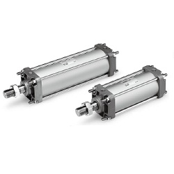
Air cylinder with auto switch (built-in magnet).
[Features]
· Air consumption reduced by up to 29% thanks to optimal size selection.
· Reduces labor time: no air cushion adjustment required thanks to non-adjustable air cushion.
· RoHS compliant.
· Mounting: basic type.
· Port thread types: Rc, NPT, G.
· *Not available without magnet.
(i)Caution
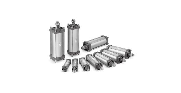
- ■ SMC Product Line
Webpages for products currently without individual pages on this site will be released on an ad-hoc basis. - Refer to the manufacturer's catalog for specification and material details.
- Product images may be representative images. Refer to the manufacturer's catalog for shape details.
- CAD data is not supported for some model numbers.
Part Number
Configured Part Number is shown.
Model Number Notation
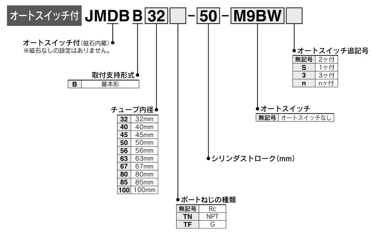
Model Number Notation
JMB Series Air Cylinder, Double Acting, Single Rod Specifications
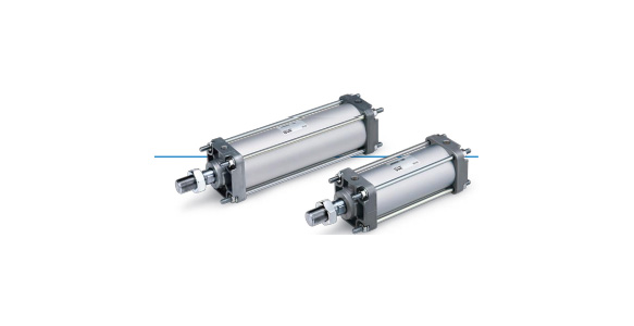
JMB Series Air Cylinder, Double Acting, Single Rod external appearance 1
JMB Series Air Cylinder, Double Acting, Single Rod external appearance 2
| Action | Double acting, single rod |
|---|---|
| Fluid | Air |
| Proof Pressure | 1.0 MPa |
| Maximum operating pressure | 0.7 MPa*1 |
| Minimum operating pressure | 0.05 MPa |
| Ambient and Fluid Temperature | 5 to 60°C |
| Lubrication | Not required (non-lubricated) |
| Piston speed* | 50 to 500 mm/s*1 |
| Stroke Length Tolerance | 0 to 2 |
| Cushioning | Non-adjustable air cushion + rubber bumper |
| Connection Port Size (Rc, NPT, G) | 1/8 (bore size 32 mm / 40 mm / 45 mm / 50 mm / 56 mm), 1/4 (bore size 63 mm / 67 mm / 80 mm / 85 mm), 3/8 (bore size 100 mm) |
| Mounting | Basic type |
*Depending on the system configuration selected, the specified speed may not be satisfied.
*1: The maximum operating pressure and piston speed differ from the MB Series.
Standard Stroke Table
| Tube Inner Diameter (mm) | Standard Stroke (mm) | Max. manufacturable stroke |
|---|---|---|
| 32 | 25, 50, 75, 100, 125, 150, 175, 200, 250, 300 | 300 |
| 40 | 25, 50, 75, 100, 125, 150, 175, 200, 250, 300 | 300 |
| 45 | 25, 50, 75, 100, 125, 150, 175, 200, 250, 300 | 300 |
| 50 | 25, 50, 75, 100, 125, 150, 175, 200, 250, 300, 350, 400 | 400 |
| 56 | 25, 50, 75, 100, 125, 150, 175, 200, 250, 300, 350, 400 | 400 |
| 63 | 25, 50, 75, 100, 125, 150, 175, 200, 250, 300, 350, 400 | 400 |
| 67 | 25, 50, 75, 100, 125, 150, 175, 200, 250, 300, 350, 400 | 400 |
| 80 | 25, 50, 75, 100, 125, 150, 175, 200, 250, 300, 350, 400, 450, 500 | 500 |
| 85 | 25, 50, 75, 100, 125, 150, 175, 200, 250, 300, 350, 400, 450, 500 | 500 |
| 100 | 25, 50, 75, 100, 125, 150, 175, 200, 250, 300, 350, 400, 450, 500 | 500 |
Weight Table
(Unit: kg)
| Tube Inner Diameter (mm) | 32 | 40 | 45 | 50 | 56 | 63 | 67 | 80 | 85 | 100 | |
|---|---|---|---|---|---|---|---|---|---|---|---|
| Basic weight | Basic type | 0.21 | 0.30 | 0.32 | 0.62 | 0.69 | 0.88 | 1.03 | 1.54 | 1.91 | 2.56 |
| Additional weight per 50 mm of stroke | 0.11 | 0.17 | 0.18 | 0.19 | 0.20 | 0.20 | 0.24 | 0.32 | 0.38 | 0.46 | |
Calculation
Example) JMDBB32-100 (Basic, ø32 [32‑mm diameter], 100 mm stroke)
- Basic weight: 0.21 (Basic, ø32 [32-mm diameter])
- Additional weight: 0.11 / 50 stroke
- Cylinder stroke: 100 stroke
0.21 + 0.11 × 100/50 = 0.43 kg
Allowable Kinetic Energy
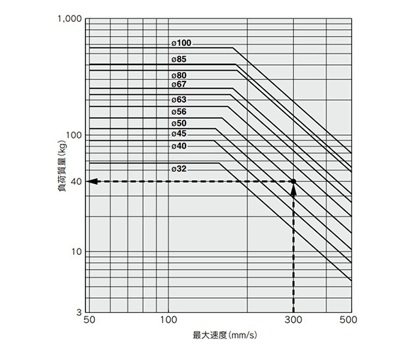
Allowable kinetic energy graph
Example) Find the upper limit of the rod-end load when an air cylinder of ø50 (50-mm diameter) is operated at 300 mm/s.
From a point indicating 300 mm/s on the horizontal axis, extend a line upward and find a point where it intersects with a line for the 50-mm bore size. Extend a line from the intersection to the left and find a load mass of 40 kg.
Allowable Lateral Load at Rod End
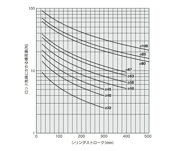
Graph of allowable lateral load at rod end
Drawing
Basic Type: JMDBB
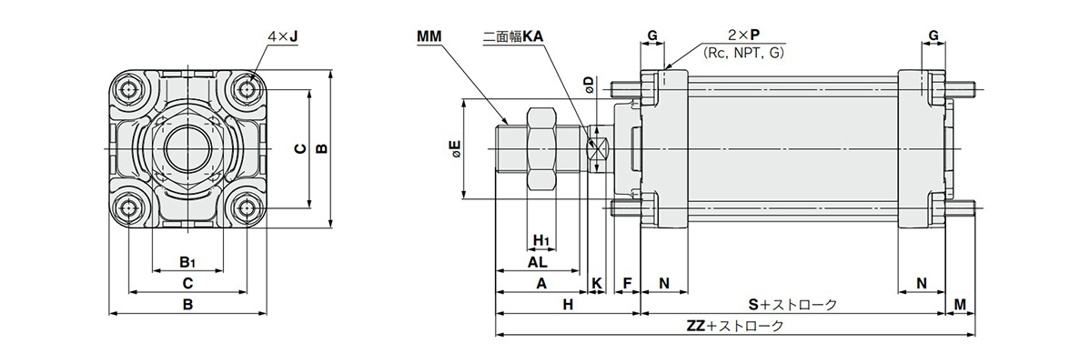
Dimensional drawings: JMDBB
(Units: mm)
| Tube inner diameter (mm) | Stroke range (mm) | A | AL | B | B1 | C | D | E | F | G | H | H1 | J | K | KA | M | MM | N | P | S | ZZ |
|---|---|---|---|---|---|---|---|---|---|---|---|---|---|---|---|---|---|---|---|---|---|
| 32 | Up to 300 | 22 | 19.5 | 42 | 17 | 31 | 10 | 24 | 8 | 9 | 38 | 6 | M5 × 0.8 | 5.5 | 8 | 8 | M10 × 1.25 | 18 | 1/8 | 63 | 109 |
| 40 | Up to 300 | 24 | 21 | 48 | 22 | 37 | 14 | 32 | 9 | 9 | 44 | 8 | M5 × 0.8 | 8 | 12 | 8 | M14 × 1.5 | 18 | 1/8 | 62 | 114 |
| 45 | Up to 300 | 24 | 21 | 52 | 22 | 41 | 14 | 32 | 9 | 9 | 44 | 8 | M5 × 0.8 | 8 | 12 | 8 | M14 × 1.5 | 18 | 1/8 | 62 | 114 |
| 50 | Up to 400 | 35 | 32 | 60 | 27 | 45 | 18 | 38 | 10 | 9 | 55 | 11 | M6 × 1 | 7 | 16 | 11 | M18 × 1.5 | 18 | 1/8 | 63 | 129 |
| 56 | Up to 400 | 35 | 32 | 65 | 27 | 50 | 18 | 38 | 10 | 9 | 55 | 11 | M6 × 1 | 7 | 16 | 11 | M18 × 1.5 | 18 | 1/8 | 63 | 129 |
| 63 | Up to 400 | 35 | 32 | 70 | 27 | 55 | 18 | 38 | 6 | 11 | 51 | 11 | M6 × 1 | 7 | 16 | 11 | M18 × 1.5 | 22 | 1/4 | 73 | 135 |
| 67 | Up to 400 | 35 | 32 | 75 | 27 | 58 | 18 | 38 | 6 | 11 | 51 | 11 | M8 × 1.25 | 7 | 16 | 11 | M18 × 1.5 | 22 | 1/4 | 73 | 135 |
| 80 | Up to 500 | 40 | 37 | 88 | 32 | 69 | 22 | 45 | 12 | 13 | 62 | 13 | M8 × 1.25 | 7 | 19 | 13 | M22 × 1.5 | 26 | 1/4 | 83 | 158 |
| 85 | Up to 500 | 40 | 37 | 95 | 32 | 74 | 22 | 45 | 12 | 13 | 62 | 13 | M10 × 1.25 | 7 | 19 | 14 | M22 × 1.5 | 26 | 1/4 | 83 | 159 |
| 100 | Up to 500 | 40 | 37 | 110 | 41 | 87 | 26 | 50 | 10 | 14 | 66 | 16 | M10 × 1.25 | 12 | 23 | 14 | M26 × 1.5 | 28 | 3/8 | 88 | 168 |
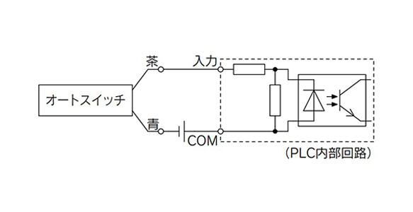
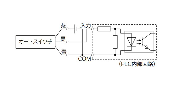
Auto Switch Connection and Example
Sink Input Specifications
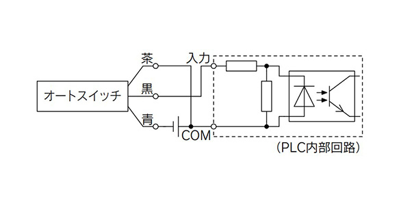
3-wire, NPN
2-wire
*Connect according to the applicable PLC input specifications, as the connection method will vary depending on the PLC input specifications.
Source Input Specifications
3-wire, PNP
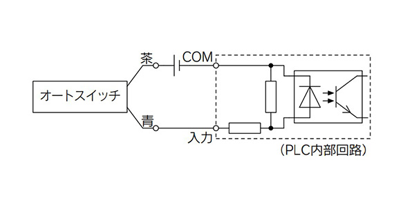
2-wire
*Connect according to the applicable PLC input specifications, as the connection method will vary depending on the PLC input specifications.
Example of AND (Series) and OR (Parallel) Connection

3-wire AND connection for NPN output (using relays)
*When using solid state auto switches, ensure the application is set up so the signals for the first 50 ms are invalid.
Precautions
- *1Allowable lateral load: The lateral load that can be applied to the piston rod end is limited. If a cylinder is used with a lateral load over the limit, it may cause air leakage due to abnormal friction of seals, galling of cylinder tubes and pistons, or abnormal friction of the bearing part. The lateral load applied to the piston rod must be within the allowable range indicated in the manufacturer's catalog. If the load exceeds the limit, install a guide or change the bore size to suit the load in order to bring the load within the allowable range.
- *2Connection with a workpiece: When a workpiece is mounted on the piston rod end, connect them aligning the center of the piston rod and the workpiece. If they are off-center, a lateral load is generated and the phenomena mentioned in *1 may occur. In order not to apply an off-center load, use of a floating joint is recommended.
- *3Simultaneous use of multiple cylinders: It is difficult to control the speed of pneumatic cylinders. The following conditions cause speed change: change in supply pressure, load, temperature and lubrication, performance difference of each cylinder, deterioration of each part over time, etc. A speed controller can be used to control the speed of multiple cylinders simultaneously for a short period of time; but depending on conditions, it may not work as desired. If multiple cylinders cannot operate simultaneously, unreasonable force is applied to the piston rod because cylinder positions may not be the same. This may cause abnormal friction of seals and bearings, and galling of cylinder tubes and pistons, etc. Do not use an application to operate several cylinders simultaneously by adjusting the cylinder speed. If operating several cylinders simultaneously is inevitable, use a highly rigid guide for the load so that the cylinder is not damaged even when the cylinder output differs slightly.
- *4 Depending on the system configuration selected, the specified speed may not be satisfied.
- *5Before using, please refer to the "Safety Precautions," the "Common Precautions," and the "Auto Switch Precautions."
- *6See the manufacturer's catalog for information other than that above.
| Part Number | Minimum order quantity | Volume Discount | Days to Ship | Cylinder (Tube) Inner Diameter (Ø) | Stroke (mm) | Port thread type | Auto Switches | Lead Wire | The number of the switches |
|---|---|---|---|---|---|---|---|---|---|
| 1 Piece(s) | Quote | 67 | 125 | Rc | M9B | 3 | 3 | ||
| 1 Piece(s) | Quote | 67 | 125 | Rc | M9BW | 0.5 | 2 | ||
| 1 Piece(s) | Quote | 67 | 150 | Rc | None | - | - | ||
| 1 Piece(s) | Quote | 67 | 150 | Rc | M9B | 3 | 1 | ||
| 1 Piece(s) | Quote | 67 | 175 | Rc | None | - | - | ||
| 1 Piece(s) | Quote | 67 | 200 | Rc | None | - | - | ||
| 1 Piece(s) | Quote | 67 | 250 | Rc | None | - | - | ||
| 1 Piece(s) | Quote | 67 | 350 | Rc | None | - | - | ||
| 1 Piece(s) | Quote | 67 | 400 | Rc | None | - | - | ||
| 1 Piece(s) | Quote | 67 | 25 | G | None | - | - | ||
| 1 Piece(s) | Quote | 67 | 50 | G | None | - | - | ||
| 1 Piece(s) | Quote | 67 | 75 | G | None | - | - | ||
| 1 Piece(s) | Quote | 67 | 100 | G | None | - | - | ||
| 1 Piece(s) | Quote | 67 | 125 | G | None | - | - | ||
| 1 Piece(s) | Quote | 67 | 150 | G | None | - | - | ||
| 1 Piece(s) | Quote | 67 | 175 | G | None | - | - | ||
| 1 Piece(s) | Quote | 67 | 200 | G | None | - | - | ||
| 1 Piece(s) | Quote | 67 | 250 | G | None | - | - | ||
| 1 Piece(s) | Quote | 67 | 300 | G | None | - | - | ||
| 1 Piece(s) | Quote | 67 | 350 | G | None | - | - | ||
| 1 Piece(s) | Quote | 67 | 400 | G | None | - | - | ||
| 1 Piece(s) | Quote | 67 | 25 | NPT | None | - | - | ||
| 1 Piece(s) | Quote | 67 | 50 | NPT | None | - | - | ||
| 1 Piece(s) | Quote | 67 | 75 | NPT | None | - | - | ||
| 1 Piece(s) | Quote | 67 | 100 | NPT | None | - | - | ||
| 1 Piece(s) | Quote | 67 | 125 | NPT | None | - | - | ||
| 1 Piece(s) | Quote | 67 | 150 | NPT | None | - | - | ||
| 1 Piece(s) | Quote | 67 | 175 | NPT | None | - | - | ||
| 1 Piece(s) | Quote | 67 | 200 | NPT | None | - | - | ||
| 1 Piece(s) | Quote | 67 | 250 | NPT | None | - | - | ||
| 1 Piece(s) | Quote | 67 | 300 | NPT | None | - | - | ||
| 1 Piece(s) | Quote | 67 | 350 | NPT | None | - | - | ||
| 1 Piece(s) | Quote | 67 | 400 | NPT | None | - | - | ||
| 1 Piece(s) | Quote | 80 | 25 | Rc | None | - | - | ||
| 1 Piece(s) | Quote | 80 | 25 | Rc | M9B | 0.5 | 2 | ||
| 1 Piece(s) | Quote | 80 | 25 | Rc | M9BW | 0.5 | 2 | ||
| 1 Piece(s) | Quote | 80 | 30 | Rc | None | - | - | ||
| 1 Piece(s) | Quote | 80 | 50 | Rc | None | - | - | ||
| 1 Piece(s) | Quote | 80 | 50 | Rc | M9BW | 0.5 | 2 | ||
| 1 Piece(s) | Quote | 80 | 50 | Rc | M9N | 0.5 | 2 | ||
| 1 Piece(s) | Quote | 80 | 80 | Rc | None | - | - | ||
| 1 Piece(s) | Quote | 80 | 80 | Rc | M9B | 0.5 | 2 | ||
| 1 Piece(s) | Quote | 80 | 100 | Rc | None | - | - | ||
| 1 Piece(s) | Quote | 80 | 125 | Rc | None | - | - | ||
| 1 Piece(s) | Quote | 80 | 150 | Rc | M9N | 0.5 | 2 | ||
| 1 Piece(s) | Quote | 80 | 150 | Rc | M9NWV | 0.5 | 2 | ||
| 1 Piece(s) | Quote | 80 | 160 | Rc | M9N | 0.5 | 2 | ||
| 1 Piece(s) | Quote | 80 | 175 | Rc | None | - | - | ||
| 1 Piece(s) | Quote | 80 | 200 | Rc | None | - | - | ||
| 1 Piece(s) | Quote | 80 | 200 | Rc | M9B | 0.5 | 2 | ||
| 1 Piece(s) | Quote | 80 | 250 | Rc | None | - | - | ||
| 1 Piece(s) | Quote | 80 | 350 | Rc | M9BW | 0.5 | 2 | ||
| 1 Piece(s) | Quote | 80 | 400 | Rc | M9BW | 0.5 | 3 | ||
| 1 Piece(s) | Quote | 80 | 450 | Rc | M9BW | 0.5 | 2 | ||
| 1 Piece(s) | Quote | 80 | 450 | Rc | M9BWV | 3 | 2 | ||
| 1 Piece(s) | Quote | 80 | 480 | Rc | None | - | - | ||
| 1 Piece(s) | Quote | 80 | 480 | Rc | M9BW | 3 | 2 | ||
| 1 Piece(s) | Quote | 80 | 500 | Rc | None | - | - | ||
| 1 Piece(s) | Quote | 80 | 500 | Rc | M9BW | 0.5 | 2 | ||
| 1 Piece(s) | Quote | 80 | 25 | G | None | - | - | ||
| 1 Piece(s) | Quote | 80 | 50 | G | None | - | - | ||
| 1 Piece(s) | Quote | 80 | 75 | G | None | - | - | ||
| 1 Piece(s) | Quote | 80 | 100 | G | None | - | - | ||
| 1 Piece(s) | Quote | 80 | 125 | G | None | - | - | ||
| 1 Piece(s) | Quote | 80 | 150 | G | None | - | - | ||
| 1 Piece(s) | Quote | 80 | 175 | G | None | - | - | ||
| 1 Piece(s) | Quote | 80 | 200 | G | None | - | - | ||
| 1 Piece(s) | Quote | 80 | 250 | G | None | - | - | ||
| 1 Piece(s) | Quote | 80 | 300 | G | None | - | - | ||
| 1 Piece(s) | Quote | 80 | 350 | G | None | - | - | ||
| 1 Piece(s) | Quote | 80 | 400 | G | None | - | - | ||
| 1 Piece(s) | Quote | 80 | 450 | G | None | - | - | ||
| 1 Piece(s) | Quote | 80 | 500 | G | None | - | - | ||
| 1 Piece(s) | Quote | 80 | 25 | NPT | None | - | - | ||
| 1 Piece(s) | Quote | 80 | 50 | NPT | None | - | - | ||
| 1 Piece(s) | Quote | 80 | 75 | NPT | None | - | - | ||
| 1 Piece(s) | Quote | 80 | 100 | NPT | None | - | - | ||
| 1 Piece(s) | Quote | 80 | 125 | NPT | None | - | - | ||
| 1 Piece(s) | Quote | 80 | 150 | NPT | None | - | - | ||
| 1 Piece(s) | Quote | 80 | 175 | NPT | None | - | - | ||
| 1 Piece(s) | Quote | 80 | 200 | NPT | None | - | - | ||
| 1 Piece(s) | Quote | 80 | 250 | NPT | None | - | - | ||
| 1 Piece(s) | Quote | 80 | 300 | NPT | None | - | - | ||
| 1 Piece(s) | Quote | 80 | 350 | NPT | None | - | - | ||
| 1 Piece(s) | Quote | 80 | 400 | NPT | None | - | - | ||
| 1 Piece(s) | Quote | 80 | 450 | NPT | None | - | - | ||
| 1 Piece(s) | Quote | 80 | 500 | NPT | None | - | - | ||
| 1 Piece(s) | Quote | 85 | 25 | Rc | None | - | - | ||
| 1 Piece(s) | Quote | 85 | 50 | Rc | None | - | - | ||
| 1 Piece(s) | Quote | 85 | 75 | Rc | M9BW | 0.5 | 2 |
Loading...
Basic Information
| Cylinder Operation Method | Double Acting | Rod Operation Method | Single Rods | Main Body Shape | Plate Cylinder |
|---|---|---|---|---|---|
| Additional Function | Standard | Environment, Applications | Standard | Cushion | Non-adjustable air cushion + rubber bumper |
| Operating Pressure(MPa) | 0.05 to 0.7 | Specifications | Built-in magnet | Type of Mount Support | Basic type |
Specification/Dimensions
-
Cylinder (Tube) Inner Diameter(Ø)
-
Stroke(mm)
-
Port thread type
- G
- NPT
- Rc
-
Auto Switches
-
Lead Wire
- 0.5
- 0.5 (M8 4-pin plug connector)
- 1
- 1 (M12 4-pin A-cord [normal-key] plug connector)
- 3
- 5
-
The number of the switches
-
type
- JMDBB
-
CAD
- 2D
- 3D
Days to Ship
-
- All
- 20 Day(s) or Less
- 31 Day(s) or Less
Specify Alterations
- The specifications and dimensions of some parts may not be fully covered. For exact details, refer to manufacturer catalogs .
Tech Support
-
Credit Card
Kartu Kredit
-
Bank TransferTransfer Bank
MISUMI Contact
MISUMI Kontak
Copyright © MISUMI Corporation All Rights Reserved.
How can we improve?Bagaimana Kami bisa meningkatkan Pelayanan?
How can we improve?Bagaimana Kami bisa meningkatkan Pelayanan?
While we are not able to respond directly to comments submitted in this form, the information will be reviewed for future improvement.
Customer Privacy Policy Walaupun Kami tidak dapat langsung menjawab saran yang ditulis di lembar ini, informasinya akan kami review untuk peningkatan pelayanan dikemudian hari
Kebijakan Privacy
Thank you for your cooperation.Terima kasih atas kerjasama anda.
While we are not able to respond directly to comments submitted in this form, the information will be reviewed for future improvement.
Please use the inquiry form.
Customer Privacy Policy Walaupun Kami tidak dapat langsung menjawab saran yang ditulis di lembar ini, informasinya akan kami review untuk peningkatan pelayanan dikemudian hari
Silahkan pergunakan Forms Permintaan.
Kebijakan Privacy