(!)Due to Microsoft's end of support for Internet Explorer 11 on 15/06/2022, this site does not support the recommended environment.
63,000 Stock items for Same Day Shipping
63,000 Item Stok untuk Pengiriman di Hari yang Sama
Search by Category / Brand
Pencarian dengan
Kategori / Merek
Search by Category Pencarian dengan Kategori
- Automation Components
A wide variety of standard and configurable components for factory automation engineers in industries such as automotive, semiconductor, packaging, medical and many more.
- Linear Motion
- Rotary Motion
- Connecting Parts
- Rotary Power Transmission
- Motors
- Conveyors & Material Handling
- Locating, Positioning, Jigs & Fixtures
- Inspection
- Sensors, Switches
- Pneumatics, Hydraulics
- Vacuum Components
- Hydraulic Equipment
- Discharging / Painting Devices
- Pipe, Tubes, Hoses & Fittings
- Modules, Units
- Heaters, Temperature Control
- Framing & Support
- Casters, Leveling Mounts, Posts
- Doors, Cabinet Hardware
- Springs, Shock Absorbers
- Adjusting, Fastening, Magnets
- Antivibration, Soundproofing Materials, Safety Products
- Fasteners
A good selection of accessories such as screws, bolts, washers and nuts that you may need for your daily engineering usage.
- Materials
Browse industrial materials ranging from heat insulating plates, sponges, to metal and plastic materials in different sizes to meet your various applications.
- Wiring Components
A wide variety of wiring parts for connecting and protecting control and PC parts including Connectors, Cables, Electric Wires, Crimping Terminals and more.
- LAN Cables / Industrial Network Cables
- Cables by Application
- Cables with Connectors
- RS232 / Personal Computers / AV Cables
- Wires/Cables
- Connectors (General Purpose)
- Crimp Terminals
- Zip Ties
- Cable Glands
- Cable Bushings/Clips/Stickers
- Screws/Spacers
- Cable Accessories
- Tubes
- Protection Tubes
- Ducts/Wiremolds
- General Purpose Tools
- Dedicated Tools
- Soldering Supplies
- Electrical & Controls
A wide variety of controls and PC parts for electrical engineers including Controls, Powers, PC parts and more.
- Cutting Tools
A wide variety of cutting tools for many uses and work materials including End Mills, Drills, Cutters, Reamers, Turning Tools and more.
- Carbide End Mills
- HSS End Mills
- Milling Cutter Inserts/Holders
- Customized Straight Blade End Mills
- Dedicated Cutters
- Turning Tools
- Drill Bits
- Screw-Hole-Related Tools
- Reamers
- Chamfering / Centering Tools
- Fixtures Related to Cutting Tools
- Step Drills
- Hole Saws
- Clean Key Cutters
- Core Drills (Tip Tools)
- Magnetic Drilling Machine Cutters
- Drill Bits for Electric Drilling Machines
- Woodworking Drill Cutters
- Drills for Concrete
- Processing Tools
A wide variety of tools and supplies used in processing including Machine Tools, Measurement Tools, Grinding and Polishing Supplies and more.
- Material Handling & Storage
A wide variety of goods used in shipment, material handling and warehouse including Tape supplies, Stretch film, Truck, Shelf, Crane and more.
- Tape Supplies
- Cushioning Materials
- Stretch Films
- Cardboard
- Plastic Bags
- PP Bands
- Magic Tapes / Tying Belts
- Rubber Bands
- Strings/Ropes
- Cable Ties
- Tags
- Labelers
- Unpacking Cutters
- Packing Support Equipment
- Cloth Sheets for Packing
- Conveyance/Dolly Carts
- Tool Wagons
- Tool Cabinets / Container Racks
- Lifters / Hand Pallets
- Container Pallets
- Storage Supplies
- Shelves/Racks
- Work Benches
- Suspended Clamps/Suspended Belts
- Jack Winches
- Chain Block Cranes
- Bottles/Containers
- Bicycle Storage Area
- Safety & General Supplies
A large variety of goods for every kind of factories and offices including Protection items, Cleaning supplies, sanitations, office supplies and more.
- Lab & Clean Room Supplies
A large variety of items used in R&D and Clean Room including research Equipment, Laboratory Essentials, Analysis Supplies, Clean Environment-Related Equipment and more.
- Press Die Components
Choose from thousands of standard stamping die components including Punch & Die, Gas Springs, Guide Components, Coil Springs and many more.
- Plastic Mold Components
Browse our wide variety of mold components including Ejector Pins, Sleeves, Leader Components, Sprue Bushings and many more.
- Ejector Pins
- Sleeves, Center Pins
- Core Pins
- Sprue bushings, Gates, and other components
- Date Mark Inserts, Recycle Mark Inserts, Pins with Gas Vent
- Undercut, Plates
- Leader Components, Components for Ejector Space
- Mold Opening Controllers
- Cooling or Heating Components
- Accessories, Others
- Components of Large Mold, Die Casting
- Injection Molding Components
Browse our injection molding components including Heating Items, Couplers, Hoses and more.
- Injection Molding Machine Products
- Accessories of Equipment
- Auxiliary Equipment
- Air Nippers
- Air Cylinders
- Air Chuck for Runner
- Chuck Board Components
- Frames
- Suction Components
- Parallel Air Chuck
- Special Air Chuck
- Chemical for Injection Molding
- Mold Maintenance
- Heating Items
- Heat Insulation Sheets
- Couplers, Plugs, One-touch Joints
- Tubes, Hoses, Peripheral Components
- Komponen Mekanis
- Linear Motion
- Rotary Motion
- Connecting Parts
- Rotary Power Transmission
- Motors
- Conveyors & Material Handling
- Locating, Positioning, Jigs & Fixtures
- Inspection
- Sensors, Switches
- Pneumatics, Hydraulics
- Vacuum Components
- Hydraulic Equipment
- Discharging / Painting Devices
- Pipe, Tubes, Hoses & Fittings
- Modules, Units
- Heaters, Temperature Control
- Framing & Support
- Casters, Leveling Mounts, Posts
- Doors, Cabinet Hardware
- Springs, Shock Absorbers
- Adjusting, Fastening, Magnets
- Antivibration, Soundproofing Materials, Safety Products
- Sekrup, Baut, Washer, Nut
- Material
- Komponen Kabel
- LAN Cables / Industrial Network Cables
- Cables by Application
- Cables with Connectors
- RS232 / Personal Computers / AV Cables
- Wires/Cables
- Connectors (General Purpose)
- Crimp Terminals
- Zip Ties
- Cable Glands
- Cable Bushings/Clips/Stickers
- Screws/Spacers
- Cable Accessories
- Tubes
- Protection Tubes
- Ducts/Wiremolds
- General Purpose Tools
- Dedicated Tools
- Soldering Supplies
- Elektrikal & Kontrol
- Peralatan Pemotong
- Carbide End Mills
- HSS End Mills
- Milling Cutter Inserts/Holders
- Customized Straight Blade End Mills
- Dedicated Cutters
- Turning Tools
- Drill Bits
- Screw-Hole-Related Tools
- Reamers
- Chamfering / Centering Tools
- Fixtures Related to Cutting Tools
- Step Drills
- Hole Saws
- Clean Key Cutters
- Core Drills (Tip Tools)
- Magnetic Drilling Machine Cutters
- Drill Bits for Electric Drilling Machines
- Woodworking Drill Cutters
- Drills for Concrete
- Peralatan Produksi
- Penanganan Material & Penyimpanan
- Tape Supplies
- Cushioning Materials
- Stretch Films
- Cardboard
- Plastic Bags
- PP Bands
- Magic Tapes / Tying Belts
- Rubber Bands
- Strings/Ropes
- Cable Ties
- Tags
- Labelers
- Unpacking Cutters
- Packing Support Equipment
- Cloth Sheets for Packing
- Conveyance/Dolly Carts
- Tool Wagons
- Tool Cabinets / Container Racks
- Lifters / Hand Pallets
- Container Pallets
- Storage Supplies
- Shelves/Racks
- Work Benches
- Suspended Clamps/Suspended Belts
- Jack Winches
- Chain Block Cranes
- Bottles/Containers
- Bicycle Storage Area
- Perlengkapan Keamanan & Umum
- Perlengkapan Sanitasi & Lab
- Komponen Press Die
- Komponen Plastik Mold
- Ejector Pins
- Sleeves, Center Pins
- Core Pins
- Sprue bushings, Gates, and other components
- Date Mark Inserts, Recycle Mark Inserts, Pins with Gas Vent
- Undercut, Plates
- Leader Components, Components for Ejector Space
- Mold Opening Controllers
- Cooling or Heating Components
- Accessories, Others
- Components of Large Mold, Die Casting
- Komponen Injeksi Moulding
- Injection Molding Machine Products
- Accessories of Equipment
- Auxiliary Equipment
- Air Nippers
- Air Cylinders
- Air Chuck for Runner
- Chuck Board Components
- Frames
- Suction Components
- Parallel Air Chuck
- Special Air Chuck
- Chemical for Injection Molding
- Mold Maintenance
- Heating Items
- Heat Insulation Sheets
- Couplers, Plugs, One-touch Joints
- Tubes, Hoses, Peripheral Components
Search by Brand Pencarian dengan Merek


This translation is a Google translation Terjemahan ini adalah terjemahan Google
- Sehubungan dengan adanya Peraturan Baru Kementerian Perdagangan No.36 Tahun 2023 tentang Pembatasan Impor Barang, MISUMI Indonesia melakukan tindakan pencegahan. Lihat informasi detailnya di sini
Due to New Regulation of Ministry Of Trade No.36 of 2023 concerning retrictions on imports of goods, MISUMI Indonesia do precautions measure. See detail information here - Nomor telepon alternatif Kontak Layanan Pelanggan : 021-29182911| 021-29182991 | 021-29182997 | 021-29182998
Alternative telephone number Contact Customer Service: 021-29182911 | 021-29182991 | 021-29182997 | 021-29182998
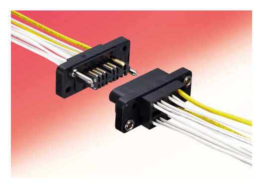
Rectangular Miniature Multi-Pin Rack / Panel Crimp Connector, QR/P1 Series【1-100 Pieces Per Package】


Compact, high-density mounted, rectangular multipole rack/panel plug-in connector QR/P. Compact crimp terminals divided into power supply and signal use.
[Features]
· The terminals have smooth insertion and removal feel, and stable contact pressure is achieved by point and blade contact, and there is some flexibility for the width corresponding to the variation in the connector connection length unique to the plug-in connection.
· The terminals are made compact by segregating according to those for power and those for signals.
· The housing internal pinout has pin 12 opposing pin 2 on one side, pins 8, 24 opposing pin 2 on both sides (total: 4 pins), and pin 32 opposing pin 3 on one side (total: 6 pins) with a greater distance of separation from other pins. These terminal pins feature a creepage distance that can adequately withstand high voltages. Therefore, the terminals can be used as power supply terminals.
· Additionally, a flame retardant material (UL9V-0) is used for the insulating material.
· Guide pins are metallic to withstand coupling impact.
· Installation to a panel or rack is achieved via a floating bush. Therefore, insertion and removal do not require the application of excessive force.
In-stock items are made-to-order, so returns and cancellations are not possible. Thank you for your understanding.
Japanese Only
Part Number
Configured Part Number is shown.
Small Rectangular Multi-Electrode Solderless Connector For Racks / Panels
QR/P1 Series
Specifications of QR/P1 Series Rack and Panel Connector
Product Standards
| QR/P1 Safety Standard Certification Ratings | |||||||
|---|---|---|---|---|---|---|---|
| Safety Standards | UL | CSA | TÜV | ||||
| Operating Temperature Range | -10 to +60°C | ||||||
| Rated voltage | Power Supply Unit | 120 V AC | 250 V AC | 125 V AC | 250 V AC | 250 V AC, 300 V DC | |
| Signal part | 125 V AC, 150 V DC | ||||||
| Rated Current | AWG#14 | 10 A | 3 A | 10 A | 3 A | 10 A | |
| AWG#16 | 8 A | ||||||
| AWG#18 | 3 A | 1 A | 3 A | 1 A | 5 A | ||
| AWG#20 | 2.5 A | ||||||
| AWG#22 | 1 A | ||||||
| AWG #24 | Power Supply Unit | 2 A | 1 A | 2 A | 1 A | ||
| Signal part | 1 A | 0.5 A | 1 A | 0.5 A | |||
| AWG#26 | 1 A | 0.5 A | 1 A | 0.5 A | |||
| AWG#28 | – | ||||||
Materials/Processing
| Part Name | Materials | Color/Finish |
|---|---|---|
| Insulator | PBT resin* | Black |
| Contacts | Phosphor bronze | Nickel base Selective gold plating |
- *UL94V-0
Power Supply Contact Configuration
Male housing (diagram viewed from wiring side), "■" indicates a contact hole for the power supply

QR/P1-8P/C(51)

QR/P1-12P-C(51)
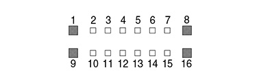
QR/P1-16P-C(51)
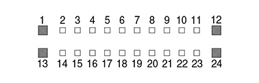
QR/P1-24P-C(51)
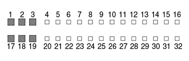
QR/P1-32P-C(51)
Product Outline Drawing And Dimensions
Housing
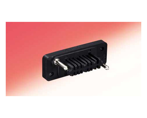
Male housing
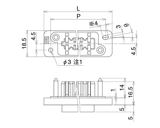
Dimensional drawing
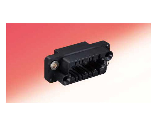
Female housing
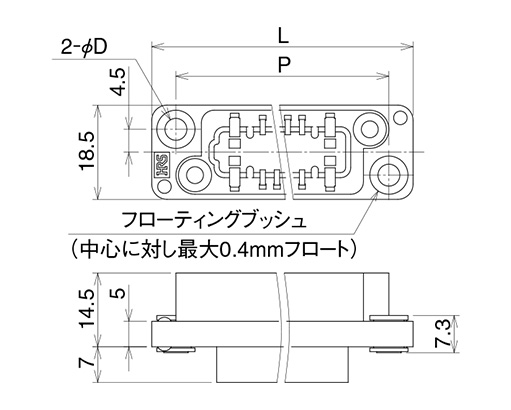
Dimensional drawing
Contact
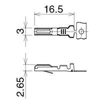
Male contact for power supply
Plating: nickel base and selective gold plating
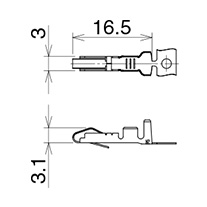
Female contact for power supply
Plating: nickel base and selective gold plating
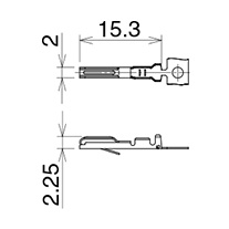
Male contact for signal
Plating: nickel base and selective gold plating
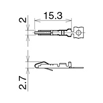
Female contact for signal
Plating: nickel base and selective gold plating
Panel mounting dimensional drawing (for S insulated case)
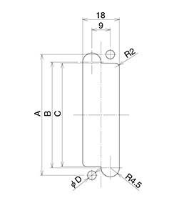
Mounting from rear of panel
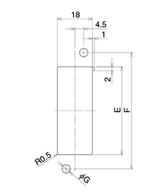
Mounting from front of panel
Units: mm, Tolerance: ±0.2
| Symbol | 8-contacts | 12-contacts | 16-contacts | 24-contacts | 32-contacts | |
|---|---|---|---|---|---|---|
| Rear surface mounting | A | 36.9 | 42 | 48.1 | 59.3 | 76 |
| B | 29.4 | 34.5 | 40.6 | 51.8 | 68.5 | |
| C | 28.4 | 33.5 | 39.6 | 50.8 | 67.5 | |
| D | 4.3 | 3.3 | 4.3 | 4.3 | 4.3 | |
| Front surface mounting | E | 22.4 | 27.5 | 33.6 | 44.8 | 61 |
| F | 36.9 | 42 | 48.1 | 59.3 | 76 | |
| G | 4.3 | 3.3 | 4.3 | 4.3 | 4.3 | |
- *The panel mounting dimensions for the P insulation case are a mirror image of the mounting dimensions for the S insulated case in which the right and left sides are reversed.
| Part Number |
|---|
| QR/P1-12S-C(51) |
| QR/P1-32P-C(51) |
| Part Number | Minimum order quantity | Volume Discount | Days to Ship | RoHS | Applicable pin/contact | Number Of Pins | Connector Type | Rated Current (A) | Connection direction | Representative Standard | Plating of part touching terminal | Product Category | Features | Contact Pitch (mm) | Operating Temperature Range (°C) |
|---|---|---|---|---|---|---|---|---|---|---|---|---|---|---|---|
| 1 Piece(s) | 16 Day(s) or more | 10 | Female | 12 | Panel Mount | 10 | Straight | UL / TUV / CSA | No terminal | Housing (plug-in connection) | Small | 2.8 | -10 – +60 | ||
| 1 Piece(s) | 16 Day(s) or more | 10 | Male | 32 | Panel Mount | 10 | Straight | UL / TUV / CSA | No terminal | Relay housing (plug-in connection) | Small | 2.8 | -10 – +60 |
Loading...
Basic Information
| Connector Shape | Rectangular | Connector series initials | P/Q/R | P/Q/R | QR/P |
|---|---|---|---|---|---|
| Allowable Voltage(V) | AC250 / AC125 | Wiring Method | Crimp | Special Notes | Power supply: 250 VAC / signal: 125 VAC (with UL CSA standards) |
Specification/Dimensions
-
Applicable pin/contact
- Male
- Female
-
Number Of Pins
-
Connector Type
- Panel Mount
- Other
-
Rated Current(A)
-
Connection direction
- Straight
-
Plating of part touching terminal
- Gold
- No terminal
-
Product Category
-
Features
- For fine power supply wires
- For fine signal wires
- For thick power wires
- For thick signal wires
- Small
-
Contact Pitch(mm)
-
Representative Standard
- UL
- TUV
- CSA
Days to Ship
-
- All
- 16 Day(s) or Less
Specify Alterations
- The specifications and dimensions of some parts may not be fully covered. For exact details, refer to manufacturer catalogs .
Tech Support
- Factory Automation, Electronics, Tools, & MRO (Maintenance, Repair and Operations)
- Tel:021-8990-4102 / FAX:021-8990-5803
- 8:30am - 5:30pm (Monday - Friday)
- Technical Inquiry
-
Credit Card
Kartu Kredit
-
Bank TransferTransfer Bank
MISUMI Contact
MISUMI Kontak
Copyright © MISUMI Corporation All Rights Reserved.
How can we improve?Bagaimana Kami bisa meningkatkan Pelayanan?
How can we improve?Bagaimana Kami bisa meningkatkan Pelayanan?
While we are not able to respond directly to comments submitted in this form, the information will be reviewed for future improvement.
Customer Privacy Policy Walaupun Kami tidak dapat langsung menjawab saran yang ditulis di lembar ini, informasinya akan kami review untuk peningkatan pelayanan dikemudian hari
Kebijakan Privacy
Thank you for your cooperation.Terima kasih atas kerjasama anda.
While we are not able to respond directly to comments submitted in this form, the information will be reviewed for future improvement.
Please use the inquiry form.
Customer Privacy Policy Walaupun Kami tidak dapat langsung menjawab saran yang ditulis di lembar ini, informasinya akan kami review untuk peningkatan pelayanan dikemudian hari
Silahkan pergunakan Forms Permintaan.
Kebijakan Privacy