
 Chat Now
Single Axis Actuators KS60 Standard/KSC60 With Cover

Brand :
MISUMI
Caution
- Please refer to dimension on website and 3D CAD instead of Economy Series promotion book.
Product Description
This is an economy item, The price is cheaper than the MISUMI standard product.
Economy Single Axis Actuators KS60 Standard/KSC60 With Cover
High Precision Compact Silent
- Achieve high-precision linear motion with the Economy Series Single Axis Actuator designed for budget-conscious applications.
- Optimize space and reduce installation complexity with this compact, lightweight actuator.
- Achieve consistent performance with a reliable mechanism offering rated loads.
- High rigidity and minimal noise ensure smooth, silent movement.
- Configure easily with multiple base lengths and accessories to meet specific requirements.


MISUMI Standard

Cheaper Price

Product Variety

3D CAD Support
Product Overview
Economy series single axis actuators are integrated drive units combining a ball screw and a linear guide, and are indispensable equipment in production and machining.Integrating a ball screw for driving and a U-shaped rail for guiding, they provide precise linear motion and can be combined with a wide range of accessories.
They are easy to incorporate into multi-purpose application designs and meet the requirements of high-precision linear motion.

Product Comparison
| MISUMI Standard Product LX3005-B1-F-400 | Economy Series C-KS6005-B1-400-F0 | |
| Accuracy | High | Standard |
| Slider Material | Chromium Molybdenum Steel | Chromium Steel |
| Body Total Length [mm] | 411 | 470 |
| Max. Stroke [mm] | 304 | 310 |
| Basic Rated Load: Dynamic Rating [N] | 9732 | 3373 |
| Basic Rated Load: Static Rating [N] | 17218 | 5625 |
| Repeat Positioning Accuracy [mm] | ±0.005 | ±0.01 |
| RoHS 10 Compliance | Compliant | Non-compliant |
Dimensional Drawing
| Precision Grade | Screw outer diameter | Screw lead | Block | Base | Motor Bracket and Attachments | Cover | |||||
 Material |  Surface Treatment | Material |  Hardness | Surface Treatment | Material | Surface Treatment | Material | Surface Treatment | |||
| Normal | 12 | 5 | 20Cr | Carburizing | S55C | 58~62 HRC | Phosphating | Aluminum Alloy | Black Anodized | Aluminum Alloy | Black Anodized |
Accuracy
| Economy Series | Base Length | Positioning Repeatability | Running Parallelism | Max. Starting Torque (N·cm) |
| C-KS40/C-KSC40 | 100 | ±0.005 | 0.03 | 1.2 |
| 150 | ||||
| 200 | ||||
| C-KS50/C-KSC50 | 150 | 2 | ||
| 200 | ||||
| 250 | ||||
| 300 | ||||
| C-KS60/C-KSC60 | 150 | 7 | ||
| 200 | ||||
| 300 | ||||
| 400 | ||||
| 500 | 0.04 | |||
| 600 | ||||
| C-KS86/C-KSC86 | 340 | 10 | ||
| 440 | ||||
| 540 | ||||
| 640 | ||||
| 740 | 0.05 | |||
| 940 | 0.06 |


Dimensional Drawing of Motor Brackets and Attachments

| Dimension | a | b | c | d | e | f |
| 60 Series | 51 | 64.35 | 5 | 14.5 | 8 | 14.5 |
Note: The appropriate sensor is NPN type photo micro sensor C-MSX671N-2M.
Motor Bracket and Attachment Selection Table by Motor Manufacturer
| Mitsubishi / Yaskawa / HCFA / Inovance / Delta Servo Motors | |||||
| Output Power | C-KS/KSC40 | C-KS/KSC50 | C-KS/KSC60 | C-KS/KSC86 | C-KS/KSC100 |
| 100W | F1 | F1 | F1 | F2 | - |
| 200W/400W | - | - | F7 | F0 | F0 |
| 750W | - | - | - | F8 | F1 |
| Panasonic Servo Motors | |||||
| Output Power | C-KS/KSC40 | C-KS/KSC50 | C-KS/KSC60 | C-KS/KSC86 | C-KS/KSC100 |
| 50W/100W | F2 | F2 | F2 | F3 | - |
| 200W/400W | - | - | F6 | F1 | - |
| 750W | - | - | - | F4 | F2 |
| Stepper Motors | |||||
| Output Power | C-KS/KSC40 | C-KS/KSC50 | C-KS/KSC60 | C-KS/KSC86 | C-KS/KSC100 |
| 42 Stepper | F3 | F3 | F5 | - | |
| 57 Stepper | - | - | F4 | F6 | - |
| 60 Stepper | - | - | F3 | F5 | - |
| 86 Stepper | - | - | - | F7 | F4 |
Specification Table

| Type | Base Length L2 (mm) | Total Length L1 (mm) | Max. Stroke | G (mm) | n | K (mm) | m | Mass (kg) | ||
| Block Qty. 1pc | Block Qty. 2pcs | Block Qty. 1pc | Block Qty. 2pcs | |||||||
| C-KS60 (Standard Type) C-KSC60 (Cover Type) | *150 | 220 | 60 | - | 25 | 2 | 100 | 2 | 1.5 | - |
| *200 | 270 | 110 | - | 50 | 2 | 100 | 2 | 1.6 | - | |
| 300 | 370 | 210 | 135 | 50 | 3 | 200 | 2 | 2.4 | 2.7 | |
| 400 | 470 | 310 | 235 | 50 | 4 | 100 | 4 | 3 | 3.3 | |
| 500 | 570 | 410 | 335 | 50 | 5 | 200 | 3 | 3.6 | 3.9 | |
| 600 | 670 | 510 | 435 | 50 | 6 | 100 | 6 | 4.2 | 4.6 | |
Load Specifications
| Type | Precision Grade | Block Qty. | Ball Screw | Block | |||||||
| Nominal Outer Diameter | Lead | Basic Dynamic Load Rating (N) | Basic Static Load Rating (N) | Basic Dynamic Load Rating (N) | Basic Static Load Rating (N) | Allowable Static Moment Pitching Mp (N·m) | Allowable Static Moment Yawing My (N·m) | Allowable Static Moment Rolling Mr (N·m) | |||
| C-KS60 (Standard Type) C-KSC60 (Cover Type) | Normal | 1 | 12 | 5 10 | 3373 | 5625 | 13230 | 21462 | 152 | 152 | 419 |
| 2 | 2107 | 3234 | 760 | 760 | 838 | ||||||
Alterations
| ⑧Drive Side Shaft End Keyway Keyway Detailed Dimensions  P.276  | KC | Machines a keyway on the drive side shaft end. 3≤KC≤P×3 KC≤F-1 KC=1mm Increment Ex. KC10 |
⑨Drive Side Shaft End Keyway (Position Specified) | KLC | The position of the keyway on the drive side shaft end can be specified. (Keyway dimensions are the same as KC.) 4≤K+S≤P×3 K+S≤F-1 K, S=1mm Increment Ex. KLC-K5-S3 |
⑩Drive Side Shaft End Wrench Flat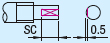 | SC | Machines a wrench flat on the drive side shaft end. 5≤SC≤P×3 SC≤F-1 SC=1mm Increment Ex. SC10 |
■Keyway Detailed Dimensions of Fixed Side P

| Shaft Dia. | b | t | ||
| Basic Dimension | Tolerance (N9) | Basic Dimension | Tolerance | |
| 6~7 | 2 | -0.004 -0.029 | 1.2 | +0.1 0 |
| 8~10 | 3 | 1.8 | ||
| 11~12 | 4 | 0 -0.03 | 2.5 | |
| 13~17 | 5 | 3.0 | ||
| 18~20 | 6 | 3.5 | ||
※When specifying keyway machining, make sure it does not interfere with other alterations.
Product Features
1. Simple design and installation2. Single Axis Actuators is Compact and lightweight
3. High precision
4. High rigidity
5. Single Axis Actuators is Low noise
6. Complete supporting accessories
Precautions
Precautions for use of Single Axis Actuators■ Please avoid using the Single Axis Actuators, single-axis drive product in the following environments.
① Dusty environment (especially containing metal powder)
② Water and oil splashing environment
③ Environment near the fire source
④ Environment containing organic solution and salt
⑤ Environment subject to direct sunlight and heat radiation
⑥ Environment exposed to strong vibration and impact
⑦ Environment containing corrosive gases and combustible gases
■ Single Axis Actuators, Single-axis drive operating environment
Operating environment: Normal temperature (without freezing or condensation)
Usage Method


Example of Use
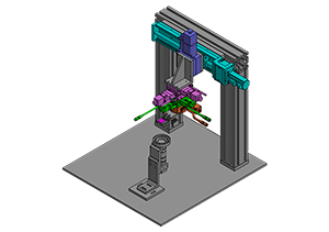
| Application Industries of Single Axis Actuators | Semiconductor |
| Intended Use | Enable the movement of the unit to be assembled through the economy series single-axis drive |
 | |
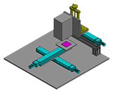
| Application Industries of Single Axis Actuators | LCD detection |
| Intended Use | It is used for the focusing mechanism of the measured object. It can be interchanged depending on the size of the measured object. |
 | |
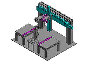
| Application Industries of Single Axis Actuators | Detection |
| Intended Use | Using the economy series single-axis drive with multiple sliders, it is possible to detect a workpiece in multiple positions or simultaneously detect multiple workpieces. |
 | |