


● This is a RoHS compliant MIL standard drip-proof DMS connector.
● In addition to the functions of the conventional MS connector, the drip-proof MS connector has waterproof and dustproof functions of IP66 class, so it can be used in a wide range of environments.
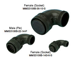
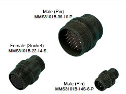
● There are 5 kinds of shell (body)
〇 Straight Type 〇 Relay Type 〇 Panel Mount Relay Type
〇 Angle Type 〇 Panel Mount Type
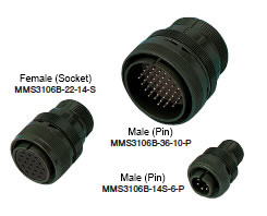
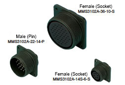
● Both male (pin) and female (socket) can be selected for each type to suit your purpose. (Excluding 10SL shell size)
● Panel mount type can be selected from 2 mounting methods.
〇 Front Mounting (mounted from the front of the panel)
〇 Rear Mounting (mounted from the rear of the panel)
● In addition to the basic position, the position of the incorrect insertion prevention key can be selected from up to 4 other angles. To prevent incorrect insertion when the same type connectors are used side by side.
●UL No. E72124
(!)Due to Microsoft's end of support for Internet Explorer 11 on 15/06/2022, this site does not support the recommended environment.
9.5 Million Products, 1,600 Brands, Free Shipping,
63,000 Stock items for Same Day Shipping
63,000 Stock items for Same Day Shipping
9.5 Juta Produk, 1,600 Merek, Gratis Pengiriman,
63,000 Item Stok untuk Pengiriman di Hari yang Sama
63,000 Item Stok untuk Pengiriman di Hari yang Sama
021-8984-0008
021-8984-0008
8:30 - 17:30 (Mon-Fri), 8:30 - 15:00 (Sat)
8:30 - 17:30 (Sen-Jum), 8:30 - 15:00 (Sab)
Search by Category / Brand
Pencarian dengan
Kategori / Merek
Search by Category Pencarian dengan Kategori
- Automation Components
A wide variety of standard and configurable components for factory automation engineers in industries such as automotive, semiconductor, packaging, medical and many more.
- Linear Motion
- Rotary Motion
- Connecting Parts
- Rotary Power Transmission
- Motors
- Conveyors & Material Handling
- Locating, Positioning, Jigs & Fixtures
- Inspection
- Sensors, Switches
- Pneumatics, Hydraulics
- Vacuum Components
- Hydraulic Equipment
- Discharging / Painting Devices
- Pipe, Tubes, Hoses & Fittings
- Modules, Units
- Heaters, Temperature Control
- Framing & Support
- Casters, Leveling Mounts, Posts
- Doors, Cabinet Hardware
- Springs, Shock Absorbers
- Adjusting, Fastening, Magnets
- Antivibration, Soundproofing Materials, Safety Products
- Fasteners
A good selection of accessories such as screws, bolts, washers and nuts that you may need for your daily engineering usage.
- Materials
Browse industrial materials ranging from heat insulating plates, sponges, to metal and plastic materials in different sizes to meet your various applications.
- Wiring Components
A wide variety of wiring parts for connecting and protecting control and PC parts including Connectors, Cables, Electric Wires, Crimping Terminals and more.
- LAN Cables / Industrial Network Cables
- Cables by Application
- Cables with Connectors
- RS232 / Personal Computers / AV Cables
- Wires/Cables
- Connectors (General Purpose)
- Crimp Terminals
- Zip Ties
- Cable Glands
- Cable Bushings/Clips/Stickers
- Screws/Spacers
- Cable Accessories
- Tubes
- Protection Tubes
- Ducts/Wiremolds
- General Purpose Tools
- Dedicated Tools
- Soldering Supplies
- Electrical & Controls
A wide variety of controls and PC parts for electrical engineers including Controls, Powers, PC parts and more.
- Cutting Tools
A wide variety of cutting tools for many uses and work materials including End Mills, Drills, Cutters, Reamers, Turning Tools and more.
- Carbide End Mills
- HSS End Mills
- Milling Cutter Inserts/Holders
- Customized Straight Blade End Mills
- Dedicated Cutters
- Turning Tools
- Drill Bits
- Screw-Hole-Related Tools
- Reamers
- Chamfering / Centering Tools
- Fixtures Related to Cutting Tools
- Step Drills
- Hole Saws
- Clean Key Cutters
- Core Drills (Tip Tools)
- Magnetic Drilling Machine Cutters
- Drill Bits for Electric Drilling Machines
- Woodworking Drill Cutters
- Drills for Concrete
- Processing Tools
A wide variety of tools and supplies used in processing including Machine Tools, Measurement Tools, Grinding and Polishing Supplies and more.
- Material Handling & Storage
A wide variety of goods used in shipment, material handling and warehouse including Tape supplies, Stretch film, Truck, Shelf, Crane and more.
- Tape Supplies
- Cushioning Materials
- Stretch Films
- Cardboard
- Plastic Bags
- PP Bands
- Magic Tapes / Tying Belts
- Rubber Bands
- Strings/Ropes
- Cable Ties
- Tags
- Labelers
- Unpacking Cutters
- Packing Support Equipment
- Cloth Sheets for Packing
- Conveyance/Dolly Carts
- Tool Wagons
- Tool Cabinets / Container Racks
- Lifters / Hand Pallets
- Container Pallets
- Storage Supplies
- Shelves/Racks
- Work Benches
- Suspended Clamps/Suspended Belts
- Jack Winches
- Chain Block Cranes
- Bottles/Containers
- Bicycle Storage Area
- Safety & General Supplies
A large variety of goods for every kind of factories and offices including Protection items, Cleaning supplies, sanitations, office supplies and more.
- Lab & Clean Room Supplies
A large variety of items used in R&D and Clean Room including research Equipment, Laboratory Essentials, Analysis Supplies, Clean Environment-Related Equipment and more.
- Press Die Components
Choose from thousands of standard stamping die components including Punch & Die, Gas Springs, Guide Components, Coil Springs and many more.
- Plastic Mold Components
Browse our wide variety of mold components including Ejector Pins, Sleeves, Leader Components, Sprue Bushings and many more.
- Ejector Pins
- Sleeves, Center Pins
- Core Pins
- Sprue bushings, Gates, and other components
- Date Mark Inserts, Recycle Mark Inserts, Pins with Gas Vent
- Undercut, Plates
- Leader Components, Components for Ejector Space
- Mold Opening Controllers
- Cooling or Heating Components
- Accessories, Others
- Components of Large Mold, Die Casting
- Injection Molding Components
Browse our injection molding components including Heating Items, Couplers, Hoses and more.
- Injection Molding Machine Products
- Accessories of Equipment
- Auxiliary Equipment
- Air Nippers
- Air Cylinders
- Air Chuck for Runner
- Chuck Board Components
- Frames
- Suction Components
- Parallel Air Chuck
- Special Air Chuck
- Chemical for Injection Molding
- Mold Maintenance
- Heating Items
- Heat Insulation Sheets
- Couplers, Plugs, One-touch Joints
- Tubes, Hoses, Peripheral Components
- Komponen Mekanis
- Linear Motion
- Rotary Motion
- Connecting Parts
- Rotary Power Transmission
- Motors
- Conveyors & Material Handling
- Locating, Positioning, Jigs & Fixtures
- Inspection
- Sensors, Switches
- Pneumatics, Hydraulics
- Vacuum Components
- Hydraulic Equipment
- Discharging / Painting Devices
- Pipe, Tubes, Hoses & Fittings
- Modules, Units
- Heaters, Temperature Control
- Framing & Support
- Casters, Leveling Mounts, Posts
- Doors, Cabinet Hardware
- Springs, Shock Absorbers
- Adjusting, Fastening, Magnets
- Antivibration, Soundproofing Materials, Safety Products
- Sekrup, Baut, Washer, Nut
- Material
- Komponen Kabel
- LAN Cables / Industrial Network Cables
- Cables by Application
- Cables with Connectors
- RS232 / Personal Computers / AV Cables
- Wires/Cables
- Connectors (General Purpose)
- Crimp Terminals
- Zip Ties
- Cable Glands
- Cable Bushings/Clips/Stickers
- Screws/Spacers
- Cable Accessories
- Tubes
- Protection Tubes
- Ducts/Wiremolds
- General Purpose Tools
- Dedicated Tools
- Soldering Supplies
- Elektrikal & Kontrol
- Peralatan Pemotong
- Carbide End Mills
- HSS End Mills
- Milling Cutter Inserts/Holders
- Customized Straight Blade End Mills
- Dedicated Cutters
- Turning Tools
- Drill Bits
- Screw-Hole-Related Tools
- Reamers
- Chamfering / Centering Tools
- Fixtures Related to Cutting Tools
- Step Drills
- Hole Saws
- Clean Key Cutters
- Core Drills (Tip Tools)
- Magnetic Drilling Machine Cutters
- Drill Bits for Electric Drilling Machines
- Woodworking Drill Cutters
- Drills for Concrete
- Peralatan Produksi
- Penanganan Material & Penyimpanan
- Tape Supplies
- Cushioning Materials
- Stretch Films
- Cardboard
- Plastic Bags
- PP Bands
- Magic Tapes / Tying Belts
- Rubber Bands
- Strings/Ropes
- Cable Ties
- Tags
- Labelers
- Unpacking Cutters
- Packing Support Equipment
- Cloth Sheets for Packing
- Conveyance/Dolly Carts
- Tool Wagons
- Tool Cabinets / Container Racks
- Lifters / Hand Pallets
- Container Pallets
- Storage Supplies
- Shelves/Racks
- Work Benches
- Suspended Clamps/Suspended Belts
- Jack Winches
- Chain Block Cranes
- Bottles/Containers
- Bicycle Storage Area
- Perlengkapan Keamanan & Umum
- Perlengkapan Sanitasi & Lab
- Komponen Press Die
- Komponen Plastik Mold
- Ejector Pins
- Sleeves, Center Pins
- Core Pins
- Sprue bushings, Gates, and other components
- Date Mark Inserts, Recycle Mark Inserts, Pins with Gas Vent
- Undercut, Plates
- Leader Components, Components for Ejector Space
- Mold Opening Controllers
- Cooling or Heating Components
- Accessories, Others
- Components of Large Mold, Die Casting
- Komponen Injeksi Moulding
- Injection Molding Machine Products
- Accessories of Equipment
- Auxiliary Equipment
- Air Nippers
- Air Cylinders
- Air Chuck for Runner
- Chuck Board Components
- Frames
- Suction Components
- Parallel Air Chuck
- Special Air Chuck
- Chemical for Injection Molding
- Mold Maintenance
- Heating Items
- Heat Insulation Sheets
- Couplers, Plugs, One-touch Joints
- Tubes, Hoses, Peripheral Components
Search by Brand Pencarian dengan Merek
Order/Quote
?
This translation is a Google translation Terjemahan ini adalah terjemahan Google
- Pembayaran dengan kartu kredit untuk sementara tidak tersedia karena kendala sistem.
Sementara waktu Anda dapat meggunakan metode Pembayaran di Muka atau QRIS.
Untuk informasi lebih lanjut, silakan hubungi Customer Service :
TEL: 021-8984-0008 E-mail: cs@misumi.co.id. WA: 08118984008.
Kami mohon maaf atas ketidaknyamanan yang terjadi.
Credit card payments are temporarily unavailable due to system issues. Meanwhile, you can use the Advance Payment method or QRIS. For further information, please contact Customer Service: TEL: 021-8984-0008 E-mail: cs@misumi.co.id. WA: 08118984008. We apologize for any inconvenience caused.
- Pemberitahuan Jadwal Pemeliharaan : Situs ini akan tidak tersedia dikarenaka jadwal pemeliharaan mulai dari 8:00 21/4/2024 sampai dengan 5:00 pada tanggal 22/4/2024. Kami mohon maaf atas ketidaknyamanan yang terjadi.
Scheduled Maintenance Notice: This site will be unavailable due to scheduled maintenance from 8:00 21/4/2024 to 5:00 (WIB) 22/4/2024. We apologize for the inconvenience. - Sehubungan dengan adanya Peraturan Baru Kementerian Perdagangan No.36 Tahun 2023 tentang Pembatasan Impor Barang, MISUMI Indonesia melakukan tindakan pencegahan. Lihat informasi detailnya di sini
Due to New Regulation of Ministry Of Trade No.36 of 2023 concerning retrictions on imports of goods, MISUMI Indonesia do precautions measure. See detail information here
Waterproof Clamp for MS Connector
- Volume Discount
Waterproof Cable Clamp of DMS Series
- IP67
Part Number
Configured Part Number is shown.
CE3057-20A-1-D
Specifications

| 型式 | 適 合 シェルサイズ | 基準単価 | スライド単価 | 適合 ケーブル外径 | |
| 1〜4個 | 5〜9個 | 10〜49個 | |||
| CE3057-4A-1-D | 10SL,12S | ¥570 | ¥550 | ¥530 | φ3.6~5.6 |
| CE3057-6A-1-D | 14S | ¥580 | ¥560 | ¥540 | φ7~9.0 |
| CE3057-8A-2-D | 16S,16 | ¥660 | ¥638 | ¥616 | φ8~10.5 |
| CE3057-10A-1-D | 18 | ¥599 | ¥580 | ¥561 | φ10.5~14.1 |
| CE3057-10A-2-D | ¥599 | ¥580 | ¥561 | φ8.5~11 | |
| CE3057-10A-3-D | ¥599 | ¥580 | ¥561 | φ6.5~8.7 | |
| CE3057-12A-1-D | 20,22 | ¥637 | ¥618 | ¥599 | φ12.5~16 |
| CE3057-12A-2-D | ¥637 | ¥618 | ¥599 | φ9.5~13 | |
| CE3057-12A-3-D | ¥637 | ¥618 | ¥599 | φ6.8~10 | |
| CE3057-12A-7-D | ¥637 | ¥618 | ¥599 | φ14.5~17 | |
| 型式 | 適 合 シェルサイズ | 基準単価 | スライド単価 | 適合 ケーブル外径 | |
| 1〜4個 | 5〜9個 | 10〜49個 | |||
| CE3057-16A-1-D | 24,28 | ¥779 | ¥760 | ¥741 | φ15~19.1 |
| CE3057-16A-2-D | ¥779 | ¥760 | ¥741 | φ13~15.5 | |
| CE3057-16A-4-D | ¥779 | ¥760 | ¥741 | φ19.1~21.5 | |
| CE3057-16A-6-D | ¥779 | ¥760 | ¥741 | φ18.5~20.0 | |
| CE3057-20A-1-D | 32,32A | ¥855 | ¥836 | ¥817 | φ22~23.8 |
| CE3057-20A-2-D | ¥900 | ¥880 | ¥860 | φ24~26.6 | |
| CE3057-20A-3-D | ¥900 | ¥880 | ¥860 | φ20~22.5 | |
| CE3057-24A-1-D | 36 | ¥1,064 | ¥1,045 | ¥1,026 | φ25~29.0 |
Lead Time

More Information

材料・仕上
| 項 目 | 材 料 | 仕 上 |
| クランプ本体、サドル | アルミ合金 | 亜鉛メッキ三価クロメート処理 |
| ブッシング | 合成ゴム | 黒色 |
| Part Number |
|---|
| CE3057-20A-1-D |
| Part Number | Minimum order quantity | Volume Discount | Days to Ship |
|---|---|---|---|
| 1 Piece(s) | Available | 16 Day(s) or more |
Loading...
Drip-proof MS (DMS)
Features
Common Specifications

● About the Waterproof Structure

MIL Standard Compliant MS Connector
Common Specifications
Applicable Wire Size and Contact Size
Appropriate wire coating stripping length is the dimension of the contact solder hole length (L size) plus about 1 ~ 3 mm. Please note that the L dimension and D dimension of the male connector (pin) and the female connector (socket) are the same. When selecting the cable, please check if the cable fits into the inner diameter of the cable clamp.| Contact | Compatible Electric Wire Size | ||||
|---|---|---|---|---|---|
| Contact Size | Solder Hole Diameter φD (mm) | Pin Contact Contacting Part Diameter φA (mm) | L (mm) | AWG | Conductor Section Area mm2 |
| #16 | 1.85 | 1.6 | 6.4 | 16 ~ 20 | 1.25 or less |
| #12 | 2.95 | 2.4 | 9.5 | 12 ~ 14 | 3.5 or less |
| #8 | 5.31 | 3.6 | 12.7 | 8 ~ 10 | 8 or less |
| #4 | 8.45 | 5.7 | 15.9 | 4 ~ 6 | 22 or less |
| #0 | 11.91 | 9.1 | 15.9 | 0 ~ 2 | 50 or less |
Electrical Properties
| Contact Resistance | Contact Size | Test Current DC | Voltage Drop | Couple the male and the female side of the connector the same way as in operating conditions, send test current, measure using the voltage drop method and fulfill the value on the left. |
|---|---|---|---|---|
| #16 | 20 A | 21 mV or lower | ||
| #12 | 35 A | 20 mV or lower | ||
| #8 | 60 A | 12 mV or lower | ||
| #4 | 110 A | 10 mV or lower | ||
| #0 | 200 A | 10 mV or lower |
Mechanical Properties
| Thermal Shock | Low Temperature | High Temperature | Carry out 5 consecutive cycles, with the low temperature and high temperature on the left as 1 cycle. The time exposed to low and high temperature must be 30 minutes or more. | ||||
|---|---|---|---|---|---|---|---|
| -55 +0℃ | +125 +3°C | ||||||
| (1) There should be no cracks or damage in the connector. (2) After completion, the voltage resistance test should be satisfied. | |||||||
| Humidity Resistance | The following voltage resistance should be satisfied. | Expose the coupled connectors and panel mount to temperature 71±2°C and relative humidity 95±3% for 14 days, and then, without drying, perform the voltage resistance test in the left table for 5 minutes. | |||||
| Test Category Symbol | VAC (r.m.s.) | ||||||
| INST | 300 | ||||||
| A | 750 | ||||||
| D | 1,350 | ||||||
| E | 1,875 | ||||||
| B | 2,775 | ||||||
| C | 4,500 | ||||||
| Corrosion | (1) There should be no exposed metal or corrosion damaging the coupling or detachment of the connector. (2) Measurement of Contact Resistance | Expose for 48 hours to salt spray with concentration 5% and temperature 35°C; after that, wash under running water and dry for 12 hours in an air-circulating chamber at temperature of 38±3°C; finally, perform contact resistance and voltage resistance tests. | |||||
| Contact Size | Test Current | Voltage Drop (or less) | |||||
| #16 | 20 A | 35 mV | |||||
| #12 | 35 | 30 | |||||
| #8 | 60 | 25 | |||||
| #4 | 110 | 20 | |||||
| #0 | 200 | 20 | |||||
| (3) The voltage resistance in the following table should be satisfied. | |||||||
| Test Category Symbol | VAC (r.m.s.) | Category Symbol | VAC (r.m.s.) | ||||
| INST | 400 | E | 2,500 | ||||
| A | 1,000 | B | 3,500 | ||||
| D | 1,800 | C | 6,000 | ||||
Environmental Properties
| Single Contact Insertion and Removal Force | Contact Size | Average | Maximum | Minimum | Insertion and removal force is measured using a randomly extracted male and female. The average force should be at or below the average values shown on the left, and 96% of all values should be at or below the maximum values and at or above the minimum values. |
|---|---|---|---|---|---|
| #16 | 0.95 kg | 1.36 kg | 0.11 kg | ||
| #12 | 1.59 | 2.27 | 0.23 | ||
| #8 | 3.18 | 4.54 | 0.34 | ||
| #4 | 4.76 | 6.8 | 0.45 | ||
| #0 | 6.35 | 9.07 | 0.91 | ||
| Contact Retention Force | Contact Size | Axial Load (kg) | Contact Size | Axial Load (kg) | It should withstand axial load in both directions as shown on the left. |
| #16 | 4.5 | #4 | 9.1 | ||
| #12 | 6.8 | #0 | 11.3 | ||
| #8 | 9.1 | ||||
| Vibration | (1) There should be no current cut-off of 10 μsec or more during the test. (2) After completion, the voltage resistance test should be satisfied. (3) There should be no disconnection of the coupling, cracks, damage or looseness in any part. | Connect the wired connector and the panel mount by the usual method, and perform a vibration test using MIL-STD-1344. During the test, pass 100 mA current through the connector, inspect interruption of the current by a suitable method, and perform a voltage resistance test and visual inspection. | |||
| Impact | (1) After completion, the requirements for contact resistance should be satisfied. (2) There should be no cracks, damage or looseness in any part. | Apply acceleration of 50 G at a 90° angle to each axis direction to the wired and coupled connector and panel mount. | |||
| Service Life | (1) The requirements for contact resistance should be satisfied. (2) There should be no electrical or mechanical abnormalities. | Remove the coupling nut of the connector and insert and remove it 600 times at a speed not exceeding 500 times per 1 hour. | |||
Contact Arrangement Table (by number of cores) View from the male (pin) connector coupling surface.
Arrangement No.
The left side is the shell size of the entire connector. The right side is the arrangement number of the contact. Together these compose the Arrangement Number.
Core Number Composition
The right side is the size of 1 contact. The left side is the number of contacts.
When ordering parts, please determine the voltage, current, number of cores, size, etc. from the table below, depending on the working environment.
Note 1: Rated current is the value for single contacts when incorporated in the connector. Please note that the rated current does not change according to the voltage.
Note 2: Rather than the size of the contact or shell, rated voltage changes by arrangement of contacts.
Note 3: In some items, rated voltage diverges by each contact even when within the same connector.
Note 4: Properties will vary depending on the test category.
| Arrangement No. | Contact Shape | Contact Composition | Rated Current (A) (Note 1) | Insulation Resistance MΩ (or higher) | Rated Voltage (Note 2) (Note 3) | Test Category Symbol (Note 4) | ||||
|---|---|---|---|---|---|---|---|---|---|---|
| Shell Size | Arrangement Number | Total Number of Cores | Core Number Composition | Contact Size | VDC or less Text shows Contact No. | VAC (r.m.s.) or less Text shows Contact No. Parentheses show voltage resistance / VAC (rms) | ||||
| 10SL | 3 | P Male (Pin) S Female (Socket) | 3 | 3 | #16 | 13 | 5000 | 700 | 500 (2000) | A |
| 4 | 2 | 2 | ||||||||
| 12S | 3 | 2 | 2 | |||||||
| 14S | 1 | 3 | 3 | |||||||
| 2 | 4 | 4 | 250 | 200 (1000) | INST | |||||
| 5 | 5 | 5 | ||||||||
| 6 | 6 | 6 | ||||||||
| 7 | 3 | 3 | 700 | 500 (2000) | A | |||||
| 9 | 2 | 2 | ||||||||
| 16S | 1 | 7 | 7 | |||||||
| 5 | 3 | 3 | ||||||||
| 8 | 5 | 5 | ||||||||
| 16 | 10 | 3 | 3 | #12 | 23 | |||||
| 18 | 1 | 10 | 10 | #16 | 13 | BCFG-700, Others-250 | BCFG-500 (2000), Others-200 (1000) | A (BCFG) INST (Others) | ||
| 4 | 4 | 4 | 1250 | 900 (2800) | D | |||||
| 5 | 3 | 2 | #12 | 23 | ||||||
| 1 | #16 | 13 | ||||||||
| 8 | 8 | 1 | #12 | 23 | 700 | 500 (2000) | A | |||
| 7 | #16 | 13 | ||||||||
| 10 | 4 | 4 | #12 | 23 | ||||||
| 11 | 5 | 5 | ||||||||
| 12 | 6 | 6 | #16 | 13 | ||||||
| 19 | 10 | 10 | ||||||||
| 20 | 5 | 5 | ||||||||
| 21 | 3 | 3 | #12 | 23 | ||||||
| 22 | 3 | 3 | #16 | 13 | 1250 | 900 (2800) | D | |||
| 20 | 2 | 1 | 1 | #0 | 150 | ABHG-1250, CDEF-700 | ABHG-900 (2800), CDEF-500 (2000) | D (ABHG) A (CDEF) | ||
| 4 | 4 | 4 | #12 | 23 | 700 | 500 (2000) | A | |||
| 7 | 8 | 8 | #16 | 13 | ||||||
| 15 | 7 | 7 | #12 | 23 | ||||||
| 16 | 9 | 2 | ||||||||
| 7 | #16 | 13 | ||||||||
| 17 | 6 | 5 | #12 | 23 | ||||||
| 1 | #16 | 13 | ||||||||
| 18 | 9 | 3 | #12 | 23 | ||||||
| 6 | #16 | 13 | ||||||||
| 22 | 6 | 3 | #8 | 46 | ||||||
| 3 | #16 | 13 | ||||||||
| 23 | 2 | 2 | #8 | 46 | ||||||
| 27 | 14 | 14 | #16 | 13 | ||||||
| 29 | 17 | 17 | ||||||||
| 22 | 2 | 3 | 3 | #8 | 46 | 1250 | 900 (2800) | D | ||
| 10 | 4 | 4 | #16 | 13 | 1750 | 1250 (3500) | E | |||
| 14 | 19 | 19 | 700 | 500 (2000) | A | |||||
| 19 | 14 | 14 | ||||||||
| 22 | 4 | 4 | #8 | 46 | ||||||
| 23 | 8 | 8 | #12 | 23 | H-1250, Others-700 | H-900 (2800), Others-500 (2000) | D (H) A (Others) | |||
| 28 | 7 | 7 | 700 | 500 (2000) | A | |||||
| 24 | 2 | 7 | 7 | 1250 | 900 (2800) | D | ||||
| 5 | 16 | 16 | #16 | 13 | 700 | 500 (2000) | A | |||
| 7 | 16 | 2 | #12 | 23 | ||||||
| 14 | #16 | 13 | ||||||||
| 10 | 7 | 7 | #8 | 46 | ||||||
| 11 | 9 | 3 | ||||||||
| 6 | #12 | 23 | ||||||||
| 20 | 11 | 2 | 1250 | 900 (2800) | D | |||||
| 9 | #16 | 13 | ||||||||
| 22 | 4 | 4 | #8 | 46 | ||||||
| 28 | 24 | 24 | #16 | 13 | 250 | 200 (1000) | INST | |||
| 28 | 6 | P Male (Pin) S Female (Socket) | 3 | 3 | #4 | 80 | 5000 | 1250 | 900 (2800) | D |
| 10 | 7 | 2 | G-1250, Others-700 | G-900 (2800), 2 #8 46 Others-500 (2000) | D (G) A (Others) | |||||
| 2 | #8 | 46 | ||||||||
| 3 | #12 | 13 | ||||||||
| 11 | 22 | 4 | 700 | 500 (2000) | A | |||||
| 18 | #16 | 13 | ||||||||
| 12 | 26 | 26 | ||||||||
| 15 | 35 | 35 | ||||||||
| 16 | 20 | 20 | ||||||||
| 20 | 14 | 10 | #12 | 23 | ||||||
| 4 | #16 | 13 | ||||||||
| 21 | 37 | 37 | ||||||||
| 32 | 1 | 5 | 2 | #0 | 150 | A-1750, Others-1250 | A-1250 (3500), Others-900 (2800) | (A) D (Others) | ||
| 3 | #12 | 23 | ||||||||
| 2 | 5 | 3 | #4 | 80 | 1750 | 1250 (3500) | E | |||
| 2 | #16 | 13 | ||||||||
| 5 | 2 | 2 | #0 | 150 | 1250 | 900 (2800) | D | |||
| 7 | 35 | 7 | #12 | 23 | ABhj-250, Others-700 | ABhj-200 (1000), Others-500 (2000) | INST (ABhj) A (Others) | |||
| 28 | #16 | 13 | ||||||||
| 8 | 30 | 6 | #12 | 23 | 700 | 500 (2000) | A | |||
| 24 | #16 | 13 | ||||||||
| 9 | 14 | 2 | #4 | 80 | 1250 | 900 (2800) | D | |||
| 12 | #16 | 13 | ||||||||
| 32A | 10 | 54 | 54 | 700 | 500 (2000) | A | ||||
| 32 | 17 | 4 | 4 | #4 | 80 | 1250 | 900 (2800) | D | ||
| 414 | 52 | 52 | #16 | 13 | 700 | 500 (2000) | A | |||
| 36 | 3 | 6 | 3 | #0 | 150 | 1250 | 900 (2800) | D | ||
| 3 | #12 | 23 | ||||||||
| 4 | 3 | 3 | #0 | 150 | A-1250, BC-700 | A-900 (2800), BC-500 (2000) | D (A) A (BC) | |||
| 5 | 4 | 4 | 700 | 500 (2000) | A | |||||
| 9 | 31 | 1 | #4 | 80 | ||||||
| 2 | #8 | 46 | ||||||||
| 14 | #12 | 23 | ||||||||
| 14 | #16 | 13 | ||||||||
| 10 | 48 | 48 | ||||||||
| 73 | 73 | 73 | ||||||||
| 48 | 5 | 100 | 1 | #8 | 46 | |||||
| 9 | #12 | 23 | ||||||||
| 90 | #16 | 13 | ||||||||
Note 2: Rather than the size of the contact or shell, rated voltage changes by arrangement of contacts.
Note 3: In some items, rated voltage diverges by each contact even when within the same connector.
Note 4: Properties will vary depending on the test category.
About Change in Mis-insertion Prevention Key Position (Angle)
Straight Connector
Outline Drawing
| Shell Size | Coupling Screw A Screw | Size (mm) | |||||
|---|---|---|---|---|---|---|---|
| Cable Entry φB ±0.3 | Effective Screw Length J ±0.3 | Total Length L or less | Outer Diameter Q ±0.8 | Conduit Screw V Screw | Screw Length W or more | ||
| 10SL | 5/8-24UNEF-2B | 9.6 | 13.49 | 34.9 | 22.22 | 5/8-24UNEF-2A | 9.53 |
| 12S | 3/4-20UNEF-2B | 9.6 | 13.5 | 42.8 | 25.4 | 5/8-24UNEF-2A | 9.5 |
| 14S | 7/8-20UNEF-2B | 12.5 | 13.5 | 42.8 | 28.6 | 3/4-20UNEF-2A | 9.5 |
| 16S | 1-20UNEF-2B | 15.6 | 13.5 | 42.8 | 31.8 | 7/8-20UNEF-2A | 9.5 |
| 16 | 1-20UNEF-2B | 15.6 | 18.3 | 52.4 | 31.8 | 7/8-20UNEF-2A | 9.5 |
| 18 | 1-1/8-18UNEF-2B | 20.2 | 18.3 | 52.4 | 34.1 | 1-20UNEF-2A | 9.5 |
| 20 | 1-1/4-18UNEF-2B | 23.0 | 18.3 | 55.6 | 37.3 | 1-3/16-18UNEF-2A | 9.5 |
| 22 | 1-3/8-18UNEF-2B | 23.2 | 18.3 | 55.6 | 40.5 | 1-3/16-18UNEF-2A | 9.5 |
| 24 | 1-1/2-18UNEF-2B | 29.5 | 18.3 | 58.7 | 43.7 | 1-7/16-18UNEF-2A | 9.5 |
| 28 | 1-3/4-18UNS-2B | 29.8 | 18.3 | 58.7 | 50.0 | 1-7/16-18UNEF-2A | 9.5 |
| 32 | 2-18UNS-2B | 37.5 | 18.3 | 61.9 | 56.4 | 1-3/4-18UNS-2A | 11.1 |
| 36 | 2-1/4-16UN-2B | 43.8 | 18.3 | 61.9 | 62.7 | 2-18UNS-2A | 12.7 |
| 48 | 3-16UN-2B | 69.1 | 18.3 | 65.1 | 81.8 | 3-16UN-2A | 15.9 |
Angled Connector
Outline Drawing
| Shell Size | Coupling Screw A Screw | Size (mm) | |||||||
|---|---|---|---|---|---|---|---|---|---|
| Cable Entry B ±0.3 | Effective Screw Length J ±0.3 | Total Length L or less | M ±0.8 | Outer Diameter Q ±0.8 | U ±0.8 | Conduit Screw V Screw | Screw Length W or more | ||
| 12S | 3/4-20UNEF-2B | 9.6 | 13.5 | 50.8 | 41.7 | 25.4 | 25.4 | 5/8-24UNEF-2A | 9.5 |
| 14S | 7/8-20UNEF-2B | 12.5 | 13.5 | 54.0 | 43.3 | 28.6 | 27.0 | 3/4-20UNEF-2A | 9.5 |
| 16S | 1-20UNEF-2B | 15.6 | 13.5 | 60.3 | 48.0 | 31.8 | 28.6 | 7/8-20UNEF-2A | 9.5 |
| 16 | 1-20UNEF-2B | 15.6 | 18.3 | 65.1 | 52.8 | 31.8 | 28.6 | 7/8-20UNEF-2A | 9.5 |
| 18 | 1-1/8-18UNEF-2B | 18.6 | 18.3 | 68.3 | 54.4 | 34.1 | 32.1 | 1-20UNEF-2A | 9.5 |
| 20 | 1-1/4-18UNEF-2B | 23.0 | 18.3 | 77.0 | 60.7 | 37.3 | 33.7 | 1-3/16-18UNEF-2A | 9.5 |
| 22 | 1-3/8-18UNEF-2B | 23.2 | 18.3 | 77.0 | 60.7 | 40.5 | 33.3 | 1-3/16-18UNEF-2A | 9.5 |
| 24 | 1-1/2-18UNEF-2B | 28.0 | 18.3 | 86.5 | 67.1 | 43.7 | 34.9 | 1-7/16-18UNEF-2A | 9.5 |
| 28 | 1-3/4-18UNS-2B | 28.2 | 18.3 | 86.5 | 67.1 | 50.0 | 38.5 | 1-7/16-18UNEF-2A | 9.5 |
| 32, 32A | 2-18UNS-2B | 35.9 | 18.3 | 95.2 | 71.8 | 56.4 | 46.4 | 1-3/4-18UNS-2A | 11.1 |
| 36 | 2-1/4-16UN-2B | 42.2 | 18.3 | 100.0 | 73.4 | 62.7 | 51.2 | 2-18UNS-2A | 12.7 |
| 48 | 3-16UN-2B | 65.9 | 18.3 | 125.4 | 86.5 | 81.8 | 59.1 | 3-16UN-2A | 15.9 |
Relay Connector
Outline Drawing
| Shell Size | Coupling Screw A Screw | Size (mm) | |||||
|---|---|---|---|---|---|---|---|
| Effective Screw Length B or more | Total Length L or less | Length to Flange M +0.4 -0 | Outer Diameter N or less | Conduit Screw V Screw | Screw Length W or more | ||
| 12S | 3/4-20UNEF-2A | 9.5 | 42.88 | 14.3 | 26.97 | 5/8-24UNEF-2A | 25.4 |
| 14S | 7/8-20UNEF-2A | 9.5 | 42.88 | 14.3 | 29.36 | 3/4-20UNEF-2A | 27.0 |
| 16S | 1-20UNEF-2A | 9.5 | 42.88 | 14.3 | 31.75 | 7/8-20UNEF-2A | 28.6 |
| 16 | 1-20UNEF-2A | 15.9 | 52.37 | 19.0 | 31.75 | 7/8-20UNEF-2A | 28.6 |
| 18 | 1-1/8-18UNEF-2A | 15.9 | 52.37 | 19.0 | 34.14 | 1-20UNEF-2A | 32.1 |
| 20 | 1-1/4-18UNEF-2A | 15.9 | 55.58 | 19.0 | 37.31 | 1-3/16-18UNEF-2A | 33.7 |
| 22 | 1-3/8-18UNEF-2A | 15.9 | 55.58 | 19.0 | 40.49 | 1-3/16-18UNEF-2A | 33.3 |
| 24 | 1-1/2-18UNEF-2A | 15.9 | 58.72 | 19.0 | 43.66 | 1-7/16-18UNEF-2A | 34.9 |
| 28 | 1-3/4-18UNS-2A | 15.9 | 58.72 | 19.0 | 50.01 | 1-7/16-18UNEF-2A | 38.5 |
| 32, 32A | 2-18UNS-2A | 15.9 | 61.93 | 19.0 | 56.36 | 1-3/4UNS-2A | 46.4 |
| 36 | 2-1/4-16UN-2A | 15.9 | 61.93 | 19.0 | 62.71 | 2-18UNS-2A | 51.2 |
| 48 | 3-16UN-2A | 15.9 | 65.07 | 15.9 | 81.76 | 3-16UN-2A | 59.1 |
Panel Mount
Outline Drawing
| Shell Size | A Screw | Size (mm) | |||||||
|---|---|---|---|---|---|---|---|---|---|
| B or more | K or less | L or less | M +0.79 | φN +0 | R ±0.13 | S ±0.79 | φT +0.25 | ||
| 10SL | 5/8-24UNEF-2A | 9.53 | 2.1 | 21.9 | 14.28 | 15.9 | 18.26 | 25.4 | 3.05 |
| 12S | 3/4-20UNEF-2A | 9.52 | 2.4 | 24.3 | 14.27 | 19.86 | 20.62 | 27.79 | 3.05 |
| 14S | 7/8-20UNEF-2A | 9.52 | 2.4 | 24.3 | 14.27 | 23.01 | 23.01 | 30.18 | 3.05 |
| 16S | 1-20UNEF-2A | 9.52 | 2.4 | 24.3 | 14.27 | 24.61 | 24.61 | 32.54 | 3.05 |
| 16 | 1-20UNEF-2A | 15.88 | 2.4 | 29.1 | 19.05 | 24.61 | 24.61 | 32.54 | 3.05 |
| 18 | 1-1/8-18UNEF-2A | 15.88 | 3.0 | 28.6 | 19.05 | 26.97 | 26.97 | 34.92 | 3.05 |
| 20 | 1-1/4-18UNEF-2A | 15.88 | 3.0 | 29.4 | 19.05 | 29.36 | 29.36 | 38.10 | 3.05 |
| 22 | 1-3/8-18UNEF-2A | 15.88 | 3.0 | 29.4 | 19.05 | 31.75 | 31.75 | 41.28 | 3.05 |
| 24 | 1-1/2-18UNEF-2A | 15.88 | 3.0 | 33.4 | 20.62 | 34.92 | 34.92 | 44.45 | 3.73 |
| 28 | 1-3/4-18UNS-2A | 15.88 | 3.0 | 33.4 | 20.62 | 39.67 | 39.67 | 50.80 | 3.73 |
| 32, 32A | 2-18UNS-2A | 15.88 | 4.3 | 33.4 | 22.22 | 44.45 | 44.45 | 57.15 | 4.39 |
| 36 | 2-1/4-16UN-2A | 15.88 | 4.3 | 33.4 | 22.22 | 49.23 | 49.23 | 63.50 | 4.39 |
| 48 | 3-16UN-2A | 15.88 | 4.3 | 34.2 | 22.22 | 66.68 | 66.68 | 82.55 | 4.39 |
Current Capacity of Entire Connector
Rated current value per 1 contact varies depending on the size of the contact, but the current capacity that can flow safely through the connector varies depending on the total number of cores. The calculation method for 14-core or less and 15-core or more is different, so they are described separately.
(1) For 14-core or less
The rated current value per 1 contact at the time of connector incorporation is multiplied by the number of cores and then multiplied by the reduction factor in the figure below. The result is the allowable current of the entire connector.
■ Current Reduction Factor Table by Number of Cores
| Total Number of Cores | 1 | 2 | 3 | 4 | 5 | 6 | 7 | 8 | 9 | 10 | 11 | 12 | 13 | 14 |
|---|---|---|---|---|---|---|---|---|---|---|---|---|---|---|
| Reduction Factor (%) | 1 | 0.943 | 0.886 | 0.829 | 0.771 | 0.714 | 0.657 | 0.6 | 0.543 | 0.486 | 0.429 | 0.371 | 0.314 | 0.257 |
Example 1: For connectors with all contacts of the same size
Rated Current Value per 1 Contact x Number of Cores x Reduction Factor = Allowable Current of Entire Connector
13 A x 2 cores x 0.943 = 24.518 A
(When Arrangement Number is 12S-3)
Therefore, 24.518 A can be used for the entire connector.
Rated Current Value per 1 Contact x Number of Cores x Reduction Factor = Allowable Current of Entire Connector
13 A x 2 cores x 0.943 = 24.518 A
(When Arrangement Number is 12S-3)
Therefore, 24.518 A can be used for the entire connector.
Example 2: For connectors with contacts of different sizes
(Contact A Rated Current x Contact A Number of Cores + Contact B Rated Current x Contact B Number of Cores) x Reduction Factor (for the total number of cores) = Allowable Current of Entire Connector
(23 A x 2 cores + 13 A x 7 cores) x 0.543 = 74.391 A
(When Arrangement Number is 20-16)
Therefore, 74.391 A can be used for the entire connector.
(2) 15-core or more
The rated current value per 1 contact is multiplied by the number of cores and 20% of that value is the allowable current of the entire connector.
Example 1: For connectors with all contacts of the same size
Rated Current Value x Number of Cores x 20% = Allowable Current of Entire Connector
13 A x 17 cores x 0.2 = 44.2 A
(When Arrangement Number is 20-29)
Therefore, 44.2 A can be used for the entire connector.
Rated Current Value x Number of Cores x 20% = Allowable Current of Entire Connector
13 A x 17 cores x 0.2 = 44.2 A
(When Arrangement Number is 20-29)
Therefore, 44.2 A can be used for the entire connector.
Example 2: For connectors with contacts of different sizes
(Contact A Rated Current x Contact A Number of Cores + Contact B Rated Current x Contact B Number of Cores) x 20% = Allowable Current of Entire Connector
(23 A x 4 cores + 13 A x 18 cores) x 0.2 = 65.2 A
(When Arrangement Number is 28-11)
Therefore, 65.2 A can be used for the entire connector.
(Contact A Rated Current x Contact A Number of Cores + Contact B Rated Current x Contact B Number of Cores) x 20% = Allowable Current of Entire Connector
(23 A x 4 cores + 13 A x 18 cores) x 0.2 = 65.2 A
(When Arrangement Number is 28-11)
Therefore, 65.2 A can be used for the entire connector.
Basic Information
| Conforming shell size | 32,32A. | Conforming cable outer diameter(mm) | 22 ~ 23.8 |
|---|
Please check the type/dimensions/specifications of the part CE3057-20A-1-D in the Waterproof Clamp for MS Connector series.
- The specifications and dimensions of some parts may not be fully covered. For exact details, refer to manufacturer catalogs .
Tech Support
- Factory Automation, Electronics, Tools, & MRO (Maintenance, Repair and Operations)
- Tel:021-8990-4102 / FAX:021-8990-5803
- 8:30am - 5:30pm (Monday - Friday)
- Technical Inquiry
-
Credit Card
Kartu Kredit
-
Bank TransferTransfer Bank
MISUMI Contact
MISUMI Kontak
Copyright © MISUMI Corporation All Rights Reserved.
How can we improve?Bagaimana Kami bisa meningkatkan Pelayanan?
How can we improve?Bagaimana Kami bisa meningkatkan Pelayanan?
While we are not able to respond directly to comments submitted in this form, the information will be reviewed for future improvement.
Customer Privacy Policy Walaupun Kami tidak dapat langsung menjawab saran yang ditulis di lembar ini, informasinya akan kami review untuk peningkatan pelayanan dikemudian hari
Kebijakan Privacy
Thank you for your cooperation.Terima kasih atas kerjasama anda.
While we are not able to respond directly to comments submitted in this form, the information will be reviewed for future improvement.
Please use the inquiry form.
Customer Privacy Policy Walaupun Kami tidak dapat langsung menjawab saran yang ditulis di lembar ini, informasinya akan kami review untuk peningkatan pelayanan dikemudian hari
Silahkan pergunakan Forms Permintaan.
Kebijakan Privacy