(!)Due to Microsoft's end of support for Internet Explorer 11 on 15/06/2022, this site does not support the recommended environment.
63,000 Stock items for Same Day Shipping
63,000 Item Stok untuk Pengiriman di Hari yang Sama
Search by Category / Brand
Pencarian dengan
Kategori / Merek
Search by Category Pencarian dengan Kategori
- Automation Components
A wide variety of standard and configurable components for factory automation engineers in industries such as automotive, semiconductor, packaging, medical and many more.
- Linear Motion
- Rotary Motion
- Connecting Parts
- Rotary Power Transmission
- Motors
- Conveyors & Material Handling
- Locating, Positioning, Jigs & Fixtures
- Inspection
- Sensors, Switches
- Pneumatics, Hydraulics
- Vacuum Components
- Hydraulic Equipment
- Discharging / Painting Devices
- Pipe, Tubes, Hoses & Fittings
- Modules, Units
- Heaters, Temperature Control
- Framing & Support
- Casters, Leveling Mounts, Posts
- Doors, Cabinet Hardware
- Springs, Shock Absorbers
- Adjusting, Fastening, Magnets
- Antivibration, Soundproofing Materials, Safety Products
- Fasteners
A good selection of accessories such as screws, bolts, washers and nuts that you may need for your daily engineering usage.
- Materials
Browse industrial materials ranging from heat insulating plates, sponges, to metal and plastic materials in different sizes to meet your various applications.
- Wiring Components
A wide variety of wiring parts for connecting and protecting control and PC parts including Connectors, Cables, Electric Wires, Crimping Terminals and more.
- LAN Cables / Industrial Network Cables
- Cables by Application
- Cables with Connectors
- RS232 / Personal Computers / AV Cables
- Wires/Cables
- Connectors (General Purpose)
- Crimp Terminals
- Zip Ties
- Cable Glands
- Cable Bushings/Clips/Stickers
- Screws/Spacers
- Cable Accessories
- Tubes
- Protection Tubes
- Ducts/Wiremolds
- General Purpose Tools
- Dedicated Tools
- Soldering Supplies
- Electrical & Controls
A wide variety of controls and PC parts for electrical engineers including Controls, Powers, PC parts and more.
- Cutting Tools
A wide variety of cutting tools for many uses and work materials including End Mills, Drills, Cutters, Reamers, Turning Tools and more.
- Carbide End Mills
- HSS End Mills
- Milling Cutter Inserts/Holders
- Customized Straight Blade End Mills
- Dedicated Cutters
- Turning Tools
- Drill Bits
- Screw-Hole-Related Tools
- Reamers
- Chamfering / Centering Tools
- Fixtures Related to Cutting Tools
- Step Drills
- Hole Saws
- Clean Key Cutters
- Core Drills (Tip Tools)
- Magnetic Drilling Machine Cutters
- Drill Bits for Electric Drilling Machines
- Woodworking Drill Cutters
- Drills for Concrete
- Processing Tools
A wide variety of tools and supplies used in processing including Machine Tools, Measurement Tools, Grinding and Polishing Supplies and more.
- Material Handling & Storage
A wide variety of goods used in shipment, material handling and warehouse including Tape supplies, Stretch film, Truck, Shelf, Crane and more.
- Tape Supplies
- Cushioning Materials
- Stretch Films
- Cardboard
- Plastic Bags
- PP Bands
- Magic Tapes / Tying Belts
- Rubber Bands
- Strings/Ropes
- Cable Ties
- Tags
- Labelers
- Unpacking Cutters
- Packing Support Equipment
- Cloth Sheets for Packing
- Conveyance/Dolly Carts
- Tool Wagons
- Tool Cabinets / Container Racks
- Lifters / Hand Pallets
- Container Pallets
- Storage Supplies
- Shelves/Racks
- Work Benches
- Suspended Clamps/Suspended Belts
- Jack Winches
- Chain Block Cranes
- Bottles/Containers
- Bicycle Storage Area
- Safety & General Supplies
A large variety of goods for every kind of factories and offices including Protection items, Cleaning supplies, sanitations, office supplies and more.
- Lab & Clean Room Supplies
A large variety of items used in R&D and Clean Room including research Equipment, Laboratory Essentials, Analysis Supplies, Clean Environment-Related Equipment and more.
- Press Die Components
Choose from thousands of standard stamping die components including Punch & Die, Gas Springs, Guide Components, Coil Springs and many more.
- Plastic Mold Components
Browse our wide variety of mold components including Ejector Pins, Sleeves, Leader Components, Sprue Bushings and many more.
- Ejector Pins
- Sleeves, Center Pins
- Core Pins
- Sprue bushings, Gates, and other components
- Date Mark Inserts, Recycle Mark Inserts, Pins with Gas Vent
- Undercut, Plates
- Leader Components, Components for Ejector Space
- Mold Opening Controllers
- Cooling or Heating Components
- Accessories, Others
- Components of Large Mold, Die Casting
- Injection Molding Components
Browse our injection molding components including Heating Items, Couplers, Hoses and more.
- Injection Molding Machine Products
- Accessories of Equipment
- Auxiliary Equipment
- Air Nippers
- Air Cylinders
- Air Chuck for Runner
- Chuck Board Components
- Frames
- Suction Components
- Parallel Air Chuck
- Special Air Chuck
- Chemical for Injection Molding
- Mold Maintenance
- Heating Items
- Heat Insulation Sheets
- Couplers, Plugs, One-touch Joints
- Tubes, Hoses, Peripheral Components
- Komponen Mekanis
- Linear Motion
- Rotary Motion
- Connecting Parts
- Rotary Power Transmission
- Motors
- Conveyors & Material Handling
- Locating, Positioning, Jigs & Fixtures
- Inspection
- Sensors, Switches
- Pneumatics, Hydraulics
- Vacuum Components
- Hydraulic Equipment
- Discharging / Painting Devices
- Pipe, Tubes, Hoses & Fittings
- Modules, Units
- Heaters, Temperature Control
- Framing & Support
- Casters, Leveling Mounts, Posts
- Doors, Cabinet Hardware
- Springs, Shock Absorbers
- Adjusting, Fastening, Magnets
- Antivibration, Soundproofing Materials, Safety Products
- Sekrup, Baut, Washer, Nut
- Material
- Komponen Kabel
- LAN Cables / Industrial Network Cables
- Cables by Application
- Cables with Connectors
- RS232 / Personal Computers / AV Cables
- Wires/Cables
- Connectors (General Purpose)
- Crimp Terminals
- Zip Ties
- Cable Glands
- Cable Bushings/Clips/Stickers
- Screws/Spacers
- Cable Accessories
- Tubes
- Protection Tubes
- Ducts/Wiremolds
- General Purpose Tools
- Dedicated Tools
- Soldering Supplies
- Elektrikal & Kontrol
- Peralatan Pemotong
- Carbide End Mills
- HSS End Mills
- Milling Cutter Inserts/Holders
- Customized Straight Blade End Mills
- Dedicated Cutters
- Turning Tools
- Drill Bits
- Screw-Hole-Related Tools
- Reamers
- Chamfering / Centering Tools
- Fixtures Related to Cutting Tools
- Step Drills
- Hole Saws
- Clean Key Cutters
- Core Drills (Tip Tools)
- Magnetic Drilling Machine Cutters
- Drill Bits for Electric Drilling Machines
- Woodworking Drill Cutters
- Drills for Concrete
- Peralatan Produksi
- Penanganan Material & Penyimpanan
- Tape Supplies
- Cushioning Materials
- Stretch Films
- Cardboard
- Plastic Bags
- PP Bands
- Magic Tapes / Tying Belts
- Rubber Bands
- Strings/Ropes
- Cable Ties
- Tags
- Labelers
- Unpacking Cutters
- Packing Support Equipment
- Cloth Sheets for Packing
- Conveyance/Dolly Carts
- Tool Wagons
- Tool Cabinets / Container Racks
- Lifters / Hand Pallets
- Container Pallets
- Storage Supplies
- Shelves/Racks
- Work Benches
- Suspended Clamps/Suspended Belts
- Jack Winches
- Chain Block Cranes
- Bottles/Containers
- Bicycle Storage Area
- Perlengkapan Keamanan & Umum
- Perlengkapan Sanitasi & Lab
- Komponen Press Die
- Komponen Plastik Mold
- Ejector Pins
- Sleeves, Center Pins
- Core Pins
- Sprue bushings, Gates, and other components
- Date Mark Inserts, Recycle Mark Inserts, Pins with Gas Vent
- Undercut, Plates
- Leader Components, Components for Ejector Space
- Mold Opening Controllers
- Cooling or Heating Components
- Accessories, Others
- Components of Large Mold, Die Casting
- Komponen Injeksi Moulding
- Injection Molding Machine Products
- Accessories of Equipment
- Auxiliary Equipment
- Air Nippers
- Air Cylinders
- Air Chuck for Runner
- Chuck Board Components
- Frames
- Suction Components
- Parallel Air Chuck
- Special Air Chuck
- Chemical for Injection Molding
- Mold Maintenance
- Heating Items
- Heat Insulation Sheets
- Couplers, Plugs, One-touch Joints
- Tubes, Hoses, Peripheral Components
Search by Brand Pencarian dengan Merek


This translation is a Google translation Terjemahan ini adalah terjemahan Google
- Sehubungan dengan adanya Peraturan Baru Kementerian Perdagangan No.36 Tahun 2023 tentang Pembatasan Impor Barang, MISUMI Indonesia melakukan tindakan pencegahan. Lihat informasi detailnya di sini
Due to New Regulation of Ministry Of Trade No.36 of 2023 concerning retrictions on imports of goods, MISUMI Indonesia do precautions measure. See detail information here - Nomor telepon alternatif Kontak Layanan Pelanggan : 021-29182911| 021-29182991 | 021-29182997 | 021-29182998
Alternative telephone number Contact Customer Service: 021-29182911 | 021-29182991 | 021-29182997 | 021-29182998
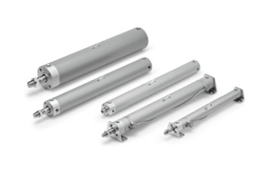
Air Cylinder, Standard Type, Double Acting, Single Rod CG1 Series

Air cylinder with female rod end available as standard.
[Features]
· Improved auto switch operability.
· Easy to adjust position.
· No trunnion mounting female thread added to basic type variation.
· Part numbers are set for products with rod-end brackets and pivot brackets. (No need to order separately.)
*See the manufacturer's catalog for detailed specifications.
*Product pictures are representations. CAD data is not supported for some model numbers.
(i)Caution
- See catalog for specification details.
- Product pictures are representations. CAD data is not supported for some model numbers.
Part Number
Configured Part Number is shown.
Air Cylinder, Standard Type, Double Acting, Single Rod CG1 Series Specifications
Air Cylinder, Standard Type, Double Acting, Single Rod CG1 Series external appearance
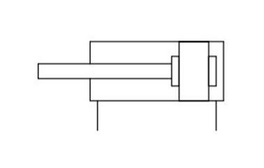
Symbol Rubber bumper
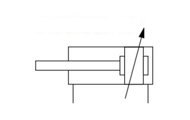
Symbol Air cushion
Specifications
| Tube Internal Diameter (mm) | 20 | 25 | 32 | 40 | 50 | 63 | 80 | 100 | ||
|---|---|---|---|---|---|---|---|---|---|---|
| Operating method | Double acting, single rod | |||||||||
| Lubrication | Not required (non-lube) | |||||||||
| Applicable fluids | Air | |||||||||
| Proof pressure | 1.5 MPa | |||||||||
| Maximum operating pressure | 1.0 MPa | |||||||||
| Minimum operating pressure | 0.05 MPa | |||||||||
| Ambient temperature and working fluid temperature | Without auto switch: -10°C to 70°C (No freezing) With auto switch: -10°C to 60°C (No freezing) | |||||||||
| Operating piston speed | 50 to 1,000 mm/s | 50 to 700 mm/s | ||||||||
| Stroke length tolerance | Up to 1,000 (st 0 to +1.4) mm, up to 1,500 (st 0 to +1.8) mm | |||||||||
| Cushioning | Rubber bumper, air cushion | |||||||||
| Mounting** | Basic type, basic type (without trunnion mounting female thread), axial foot type, rod-end flange type, head-end flange type, rod-end trunnion type, head-end trunnion type, clevis type | |||||||||
| Allowable kinetic energy (J) | Rubber bumper | Rod end male thread | 0.28 | 0.41 | 0.66 | 1.20 | 2.00 | 3.40 | 5.90 | 9.90 |
| Rod end female thread | 0.11 | 0.18 | 0.29 | 0.52 | 0.91 | 1.54 | 2.71 | 4.54 | ||
| Air cushion | Rod end male thread | R: 0.35 H: 0.42 | R: 0.56 H: 0.65 | 0.91 | 1.80 | 3.40 | 4.90 | 11.80 | 16.70 | |
| Rod end female thread | 0.11 | 0.18 | 0.29 | 0.52 | 0.91 | 1.54 | 2.71 | 4.54 | ||
- *R: rod side, H: head side
- *Cylinder sizes ø80 (80‑mm diameter) and ø100 (100‑mm diameter) do not have basic (without trunnion mounting female thread), rod trunnion or head trunnion types. Foot, flange and clevis types of cylinder sizes ø20 to ø63 (20‑ to 63‑mm diameter) do not have trunnion mounting female thread. Operate the cylinder within the allowable kinetic energy.
Standard Strokes
(Unit: mm)
| Tube I.D. | Standard strokeNote 1) | Maximum manufacturable strokeNote 2) |
|---|---|---|
| 20 | 25, 50, 75, 100, 125, 150, 200 | 201 to 1,500 |
| 25 | 25, 50, 75, 100, 125, 150, 200, 250, 300 | 301 to 1,500 |
| 32 | ||
| 40 | ||
| 50/63 | ||
| 80 | ||
| 100 |
Note 1) Intermediate strokes not listed above are produced to order.
Manufacture of intermediate strokes at 1 mm intervals is possible. (Spacers are not used.)
Note 2) The maximum manufacturable stroke shows the long stroke.
Note 3) Applicable strokes should be confirmed according to the usage. For details, refer to "Air Cylinders Model Selection" in the manufacturer's catalog.
In addition, products that exceed the standard stroke may not be able to fulfill the specifications due to deflection, etc.
Mounting Procedure
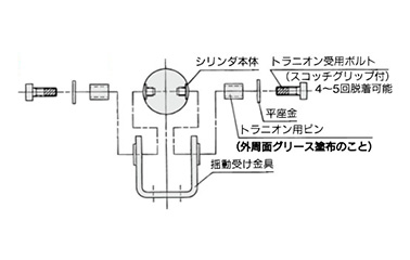
Mounting procedure for trunnion: ø20 to ø63 (20‑ to 63‑mm diameter)
Follow the procedures in the above figure when mounting a pivot bracket on the trunnion.
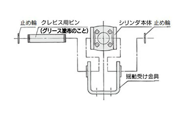
Mounting procedure for clevis: ø20 to ø63 (20‑ to 63‑mm diameter)
Follow the procedures in the above figure when mounting a pivot bracket on the clevis.
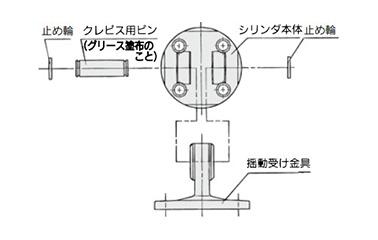
Mounting procedure for clevis: ø80 (80‑mm diameter), ø100 (100‑mm diameter)
Follow the procedures in the above figure when mounting a pivot bracket on the clevis.
Dimensional Outline Drawing (Dimensions Other Than Those Shown Below Are the Same As the Standard Type)
(Unit: mm)
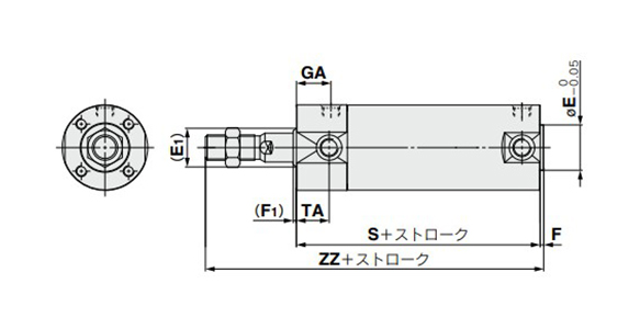
Rubber bumper dimensional outline drawing
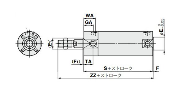
Air cushion dimensional outline drawing
| Tube I.D. | (E1) | *E | (F1) | *F | GA | S | TA | WA | ZZ | |||
|---|---|---|---|---|---|---|---|---|---|---|---|---|
| Rc | NPT | G | Male thread | Female thread | ||||||||
| 32 | 17 | 18 | 2 | 2 | 18 | 16.5 | 77 (85) | 17 | 22 | 119 (127) | 93 (101) | |
| 40 | 21 | 25 | 2 | 2 | 19 | 19 | 84 (93) | 18 | 23 | 136 (145) | 101 (110) | |
| 50 | 26 | 30 | 2 | 2 | 21 | 21 | 97 (109) | 20 | 25 | 157 (169) | 115 (127) | |
| 63 | 26 | 32 | 2 | 2 | 21 | 21 | 97 (109) | 20 | 25 | 157 (169) | 115 (127) | |
| 80 | 32 | 40 | 3 | 3 | 28 | 25.5 | 116 (130) | - | 32 | 190 (204) | 138 (152) | |
| 100 | 37 | 50 | 3 | 3 | 29 | 26.5 | 117 (131) | - | 33 | 119 (205) | 142 (156) | |
- *Dimensions marked with * are the same as the standard type.
- *Dimensions inside () are for long stroke.
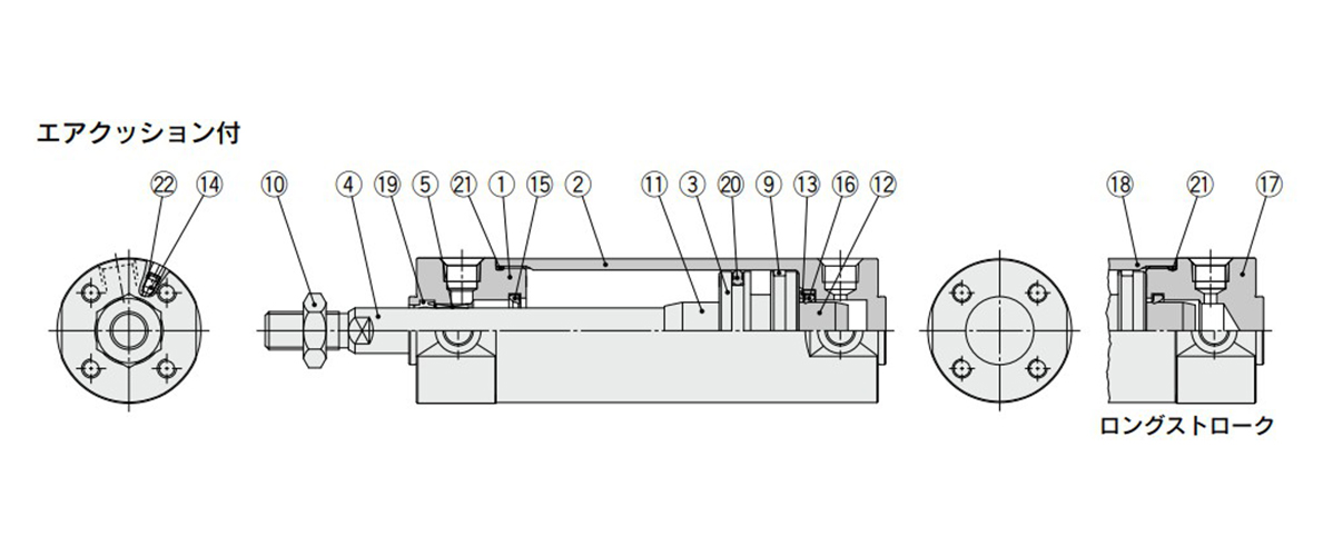
Structural drawing
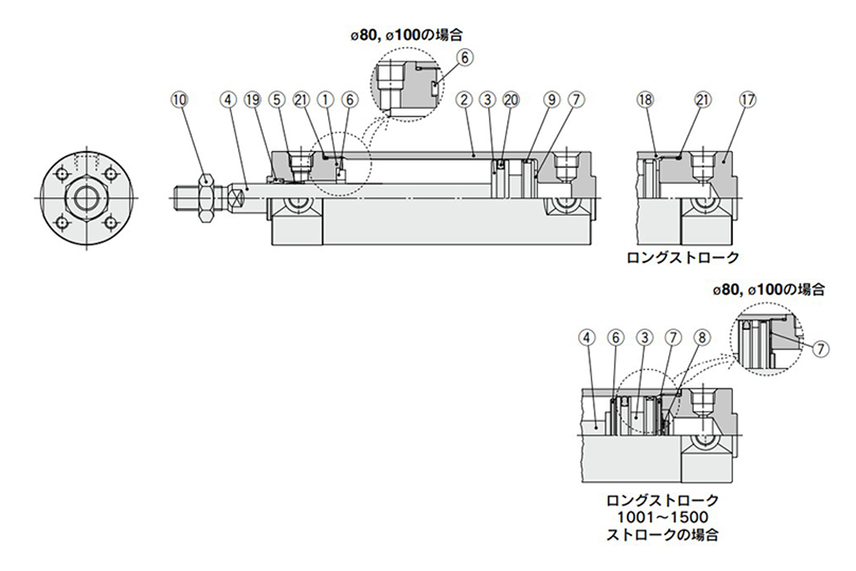
Rubber bumper structural drawing
Rubber bumper structural drawing
Component Parts
| Number | Description | Material | Note | |
|---|---|---|---|---|
| 1 | Rod Cover | Aluminum Alloy | Hard Anodize | |
| 2 | Tube cover | Aluminum Alloy | Hard Anodize | |
| 3 | Piston | Aluminum Alloy | - | |
| 4 | Piston rod | Stainless steel | For ø20 (20‑mm diameter), ø25 (25‑mm diameter) with built-in magnet | |
| Carbon steel* | Hard chrome plating* | |||
| 5 | Bushing | Resin/Copper alloy (Multiple layers) | - | |
| 6 | Dampers | Resin | ø32 (32‑mm diameter) or larger is common | |
| 7 | Dampers | Resin | ||
| 8 | Retaining Ring | Stainless steel | Not available for ø80 (80‑mm diameter), ø100 (100‑mm diameter) | |
| 9 | Wear ring | Resin | - | |
| 10 | Rod-end nut | Carbon steel | Zinc chromate | |
| 11 | Cushion ring A | Aluminum Alloy | - | |
| 12 | Cushion ring B | Aluminum Alloy | - | |
| 13 | Seal retainer | Rolled steel | Zinc chromate | |
| 14 | Cushion valve | ø40 (40‑mm diameter) or smaller | Carbon steel | Electroless nickel plating |
| ø50 (diameter 50 mm) or more | Steel wire | Zinc chromate | ||
| 15 | Cushion seal A | Urethane | ø32 (32‑mm diameter) or larger is common | |
| 16 | Cushion seal B | Urethane | ||
| 17 | Head cover | Aluminum Alloy | Hard Anodize | |
| 18 | Cylinder tube | Aluminum Alloy | Hard Anodize | |
| 19 | Rod Gasket | NBR | - | |
| 20 | Piston Gasket | NBR | - | |
| 21 | Tube gasket | NBR | - | |
| 22 | Valve seal | NBR | - | |
Note) For cylinders with auto switches, the magnet is installed in the piston.
*The material for ø20 (20‑mm diameter) and ø25 (25‑mm diameter) cylinders with auto switches is stainless steel.
*See the manufacturer's catalog for product information other than the above.
| Part Number |
|---|
| CDG1LA50-1297Z-A93 |
| CDG1ZA50-1297Z |
| Part Number | Minimum order quantity | Volume Discount | Days to Ship | Cylinder (Tube) Inner Diameter (Ø) | Stroke (mm) | Environment, Applications | Cushion | Specifications | Port thread type | Auto Switches | Lead Wire | The number of the switches | Swinging Receiving Metal | Rod Tip Metal Fitting | Type of Mount Support | Rod Tip Shape | Bellows | Custom-made Specifications |
|---|---|---|---|---|---|---|---|---|---|---|---|---|---|---|---|---|---|---|
| 1 Piece(s) | Quote | 50 | 1,297 | Standard | Air cushion | Built-in magnet | Rc | A93 | 0.5 | 2 | Without bracket | Without bracket | Axial foot type | Male rod end | Without rod boot | None | ||
| 1 Piece(s) | Quote | 50 | 1,297 | Standard | Air cushion | Built-in magnet | Rc | Without auto switch | - | - | Without bracket | Without bracket | Basic (without trunnion mounting female thread) | Male rod end | Without rod boot | None |
Loading...
Basic Information
| Cylinder Operation Method | Double Acting | Rod Operation Method | Single Rods | Main Body Shape | Standard |
|---|---|---|---|---|---|
| Additional Function | Standard | Operating Pressure(MPa) | 0.05 to 1.0 |
Specification/Dimensions
-
Cylinder (Tube) Inner Diameter(Ø)
-
Environment, Applications
- Standard
- Low Speed
- Heat Resistant
-
Cushion
-
Specifications
- Built-in magnet
- Without magnet
-
Port thread type
- M5 × 0.8
- G
- NPT
- Rc
-
Auto Switches
- G5BA
- G5NB
- G5NT
- G5P
- G5PW
- F7BA
- F7BV
- F7BWV
- F7PW
- H7B
- H7BA
- H7BW
- H7C
- H7NF
- H7NW
- H7PW
- H7A1
- H7A2
- F9G
- F9H
- M9B
- M9BA
- M9BAV
- M9BV
- M9BW
- M9BWV
- M9N
- M9NA
- M9NAV
- M9NV
- M9NW
- M9NWV
- M9P
- M9PA
- M9PAV
- M9PV
- M9PW
- M9PWV
- B53
- B54
- B59W
- G59
- G59F
- G59W
- K59
- K59W
- B64
- A73
- A73H
- C73
- C73C
- C76
- A79W
- F79
- J79
- J79C
- J79W
- A80
- A80H
- C80
- C80C
- A90
- A90V
- A93
- A93V
- A96
- A96V
- Without auto switch
- Without switch
-
Lead Wire
- 0.5
- 0.5 (M8 3-pin plug connector)
- 0.5 (M8 4-pin plug connector)
- 0.5 (M12 4-pin A-cord [normal-key] plug connector)
- 1
- 1 (M8 3-pin plug connector)
- 1 (M8 4-pin plug connector)
- 1 (M12 4-pin A-cord [normal-key] plug connector)
- 3
- 5
- None
-
The number of the switches
-
Swinging Receiving Metal
- Shipped with pivot bracket
- Without bracket
-
Rod Tip Metal Fitting
- Single knuckle joint
- U-Shaped Knuckle Joint
- Without bracket
-
Type of Mount Support
- Axial foot type
- Basic (without trunnion mounting female thread)
- Basic type
- Basic type (without trunnion mounting female thread)
- Clevis shape
- Head-end flange
- Head end trunnion type
- Rod-end flange type
- Rod end trunnion type
-
Rod Tip Shape
- Female rod end
- Male rod end
-
Bellows
-
Custom-made Specifications
- Cold-resistant cylinder (-40 to 70°C)
- Heat-resistant cylinder (-10 to 150°C)
- Low speed cylinder (5 to 50 mm/s)
- Low speed cylinder (10 to 50 mm/s)
- Auto switch rail mounting type (A type)
- Auto switch rail mounting type (B type)
- Cylinder with built-in shock absorber on the head cover side
- Double clevis pin and double knuckle pin material: stainless steel
- Double knuckle joint with spring pin
- Fluororubber seal
- Grease for food processing equipment
- Head cover axial port
- Larger pipe connection port throttle diameter
- Material: stainless steel
- None
- PTFE grease
- Tandem type cylinder
- With coil scraper
- With powerful scraper
-
type
- CDG1
- CG1
-
Stroke(mm)
- 1
- 1,000
- 1,005
- 1,010
- 1,015
- 1,020
- 1,025
- 1,030
- 1,040
- 1,045
- 1,050
- 1,055
- 1,060
- 1,065
- 1,070
- 1,072
- 1,074
- 1,075
- 1,080
- 1,085
- 1,090
- 1,095
- 1,100
- 1,105
- 1,110
- 1,111
- 1,120
- 1,125
- 1,130
- 1,135
- 1,136
- 1,140
- 1,143
- 1,145
- 1,150
- 1,155
- 1,160
- 1,165
- 1,170
- 1,171
- 1,175
- 1,180
- 1,185
- 1,190
- 1,199
- 1,200
- 1,201
- 1,208
- 1,210
- 1,215
- 1,220
- 1,225
- 1,230
- 1,240
- 1,250
- 1,251
- 1,255
- 1,256
- 1,257
- 1,260
- 1,270
- 1,275
- 1,280
- 1,290
- 1,295
- 1,297
- 1,300
- 1,310
- 1,320
- 1,325
- 1,330
- 1,340
- 1,350
- 1,360
- 1,365
- 1,370
- 1,375
- 1,380
- 1,385
- 1,400
- 1,410
- 1,420
- 1,425
- 1,440
- 1,450
- 1,460
- 1,465
- 1,470
- 1,480
- 1,500
- 2
- 3
- 4
- 5
- 6
- 7
- 8
- 10
- 12
- 13
- 14
- 15
- 16
- 17
- 18
- 19
- 20
- 21
- 22
- 23
- 24
- 25
- 26
- 27
- 28
- 29
- 30
- 31
- 32
- 33
- 34
- 35
- 36
- 37
- 38
- 39
- 40
- 41
- 42
- 43
- 44
- 45
- 46
- 47
- 48
- 49
- 50
- 51
- 52
- 53
- 54
- 55
- 56
- 57
- 58
- 59
- 60
- 61
- 62
- 63
- 64
- 65
- 66
- 67
- 68
- 69
- 70
- 71
- 72
- 73
- 74
- 75
- 76
- 77
- 78
- 79
- 80
- 81
- 82
- 83
- 84
- 85
- 86
- 87
- 88
- 89
- 90
- 91
- 92
- 93
- 94
- 95
- 96
- 97
- 98
- 99
- 100
- 101
- 102
- 103
- 104
- 105
- 106
- 107
- 108
- 109
- 110
- 111
- 112
- 113
- 114
- 115
- 116
- 117
- 118
- 119
- 120
- 121
- 122
- 123
- 124
- 125
- 126
- 127
- 128
- 129
- 130
- 131
- 132
- 133
- 134
- 135
- 136
- 137
- 138
- 139
- 140
- 141
- 142
- 143
- 144
- 145
- 146
- 147
- 149
- 150
- 151
- 152
- 153
- 154
- 155
- 156
- 157
- 159
- 160
- 162
- 163
- 165
- 166
- 167
- 168
- 169
- 170
- 172
- 173
- 175
- 176
- 177
- 178
- 179
- 180
- 181
- 182
- 183
- 185
- 186
- 187
- 188
- 190
- 191
- 192
- 193
- 195
- 198
- 200
- 201
- 202
- 203
- 204
- 205
- 206
- 207
- 208
- 209
- 210
- 212
- 213
- 214
- 215
- 216
- 218
- 220
- 222
- 223
- 225
- 226
- 227
- 228
- 229
- 230
- 231
- 232
- 233
- 234
- 235
- 236
- 237
- 238
- 240
- 243
- 245
- 246
- 247
- 250
- 251
- 252
- 253
- 254
- 255
- 256
- 257
- 260
- 262
- 264
- 265
- 266
- 268
- 270
- 273
- 275
- 276
- 277
- 278
- 280
- 281
- 282
- 283
- 285
- 287
- 288
- 290
- 291
- 292
- 293
- 295
- 297
- 298
- 300
- 301
- 302
- 303
- 304
- 305
- 306
- 307
- 308
- 310
- 312
- 313
- 315
- 316
- 320
- 323
- 324
- 325
- 326
- 327
- 328
- 329
- 330
- 334
- 335
- 336
- 338
- 339
- 340
- 342
- 343
- 345
- 346
- 349
- 350
- 351
- 352
- 355
- 359
- 360
- 362
- 363
- 365
- 368
- 369
- 370
- 371
- 372
- 374
- 375
- 377
- 378
- 380
- 381
- 382
- 383
- 384
- 385
- 386
- 387
- 390
- 393
- 395
- 396
- 400
- 401
- 402
- 404
- 405
- 406
- 407
- 410
- 412
- 414
- 415
- 416
- 418
- 419
- 420
- 422
- 424
- 425
- 426
- 427
- 428
- 430
- 432
- 435
- 436
- 440
- 444
- 445
- 450
- 451
- 452
- 455
- 457
- 460
- 463
- 465
- 470
- 471
- 472
- 473
- 475
- 476
- 480
- 481
- 483
- 485
- 488
- 490
- 493
- 495
- 496
- 499
- 500
- 501
- 502
- 503
- 505
- 506
- 508
- 510
- 512
- 513
- 515
- 517
- 520
- 523
- 525
- 527
- 528
- 530
- 532
- 533
- 535
- 540
- 542
- 543
- 545
- 547
- 548
- 550
- 551
- 552
- 555
- 558
- 560
- 562
- 565
- 570
- 575
- 578
- 580
- 584
- 585
- 590
- 591
- 595
- 596
- 598
- 600
- 605
- 606
- 607
- 610
- 615
- 620
- 621
- 622
- 624
- 625
- 626
- 630
- 635
- 640
- 641
- 642
- 645
- 646
- 650
- 652
- 653
- 655
- 660
- 662
- 665
- 666
- 670
- 672
- 675
- 680
- 685
- 690
- 692
- 695
- 696
- 700
- 705
- 706
- 710
- 715
- 720
- 725
- 730
- 735
- 738
- 740
- 745
- 748
- 750
- 752
- 753
- 754
- 755
- 757
- 760
- 762
- 764
- 765
- 768
- 769
- 770
- 772
- 775
- 779
- 780
- 785
- 790
- 795
- 800
- 805
- 807
- 810
- 815
- 816
- 819
- 820
- 825
- 830
- 832
- 835
- 839
- 840
- 843
- 845
- 850
- 855
- 860
- 865
- 870
- 875
- 880
- 885
- 888
- 890
- 895
- 900
- 905
- 910
- 915
- 920
- 921
- 925
- 928
- 930
- 935
- 940
- 945
- 947
- 950
- 952
- 955
- 957
- 960
- 964
- 965
- 970
- 975
- 979
- 980
- 985
- 990
- 995
-
CAD
- 2D
- 3D
Days to Ship
-
- All
- Same day
- 20 Day(s) or Less
- 31 Day(s) or Less
- 35 Day(s) or Less
- 40 Day(s) or Less
- 49 Day(s) or Less
- 53 Day(s) or Less
- 56 Day(s) or Less
- 58 Day(s) or Less
- 59 Day(s) or Less
Specify Alterations
- The specifications and dimensions of some parts may not be fully covered. For exact details, refer to manufacturer catalogs .
Tech Support
- Factory Automation, Electronics, Tools, & MRO (Maintenance, Repair and Operations)
- Tel:021-8990-4102 / FAX:021-8990-5803
- 8:30am - 5:30pm (Monday - Friday)
- Technical Inquiry
-
Credit Card
Kartu Kredit
-
Bank TransferTransfer Bank
MISUMI Contact
MISUMI Kontak
Copyright © MISUMI Corporation All Rights Reserved.
How can we improve?Bagaimana Kami bisa meningkatkan Pelayanan?
How can we improve?Bagaimana Kami bisa meningkatkan Pelayanan?
While we are not able to respond directly to comments submitted in this form, the information will be reviewed for future improvement.
Customer Privacy Policy Walaupun Kami tidak dapat langsung menjawab saran yang ditulis di lembar ini, informasinya akan kami review untuk peningkatan pelayanan dikemudian hari
Kebijakan Privacy
Thank you for your cooperation.Terima kasih atas kerjasama anda.
While we are not able to respond directly to comments submitted in this form, the information will be reviewed for future improvement.
Please use the inquiry form.
Customer Privacy Policy Walaupun Kami tidak dapat langsung menjawab saran yang ditulis di lembar ini, informasinya akan kami review untuk peningkatan pelayanan dikemudian hari
Silahkan pergunakan Forms Permintaan.
Kebijakan Privacy